Houdini に新しい Car RBD Rig ツールが実装され、車のシミュレーション設定が大幅に簡易化されました。以下のチュートリアルでは、この新しいツールを使ってリアルな車の走行シミュレーションを作成し、RBD Bullet Solver で車の衝突に統合する方法を紹介していきます。
ステップ 1 - アセットの準備
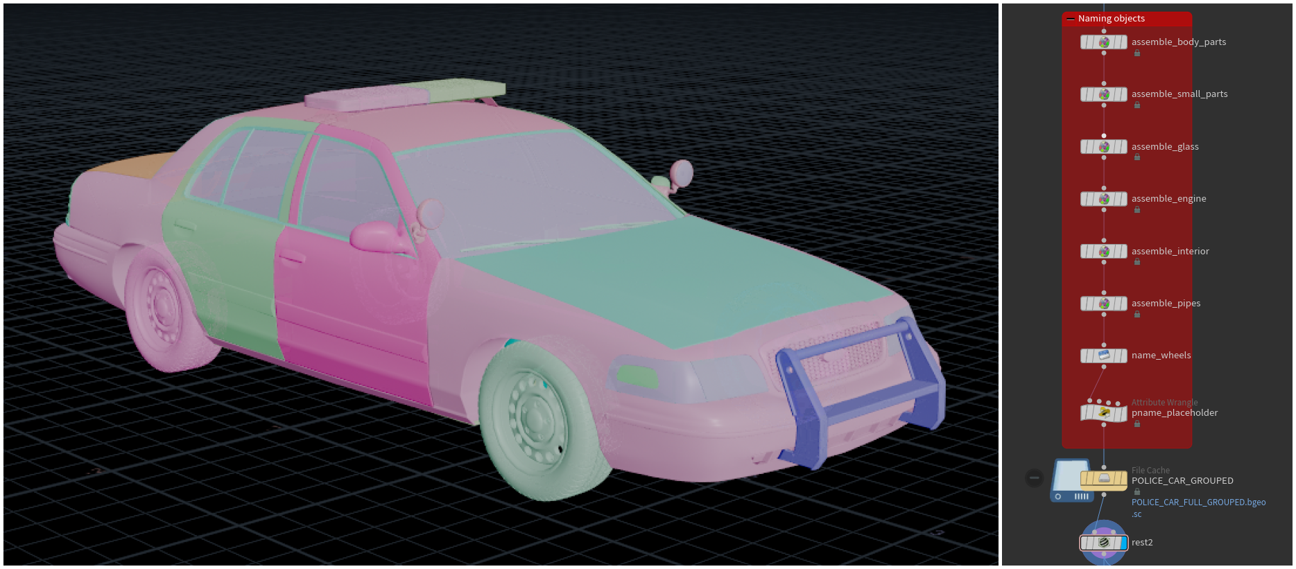
どの RBD シミュレーションも、はじめに使用するジオメトリを作成し、シミュレーションのための準備をする必要があります。今回はクラウン・ビクトリアの警察車両モデルを用意しましたが、主要パーツをグループ化して命名するほか、大きな相貫を少しクリーンアップする必要があります。
ボンネットやトランク、タイヤ、ボディなど、大まかなグループに分類できそうなパーツを全て選んでおきます。目立つ相関箇所は修正するか、不要であれば丸ごと削除します。次に Assemble ノードを使って、本体、細かい金属パーツ、ガラス、エンジン、車内、パイプ、タイヤにプレフィックスを設定し、だいたいの部位ごとにグループ化します。
RBD sim で name アトリビュートが調整されても車を変形できるよう、一時的な名称(ここでは @pname)も設定しておきましょう。最後に Rest Position ノードを配置し、後から元の位置を参照できるようにします。破砕の工程でテクスチャをテストする時のために、Material ノードも配置します。
ステップ 2 - 車のリグとアニメーション
次に、衝突前の動きとなる車のアニメーションが必要です。RBD Car Rig ノードのサスペンションリグを使うとリアルな車アニメーションだけでなく、後ほど主要シミュレーションの拘束設定をする時にも役立ちます。RBD Car Rig ノードに入ってタイヤを選択し、Quick Setups で RBD Bullet Solver メニューを表示します。Car Rig のパラメータを調整して、この後リグ付けする車のタイプをより的確に表現し、より精確なシミュレーションを得られるようにします。Quick Setups では、カメラトラックのアトリビュートも作成でき、これにより車をフォローしたいショットで、3台の異なるカメラを使用することができます。
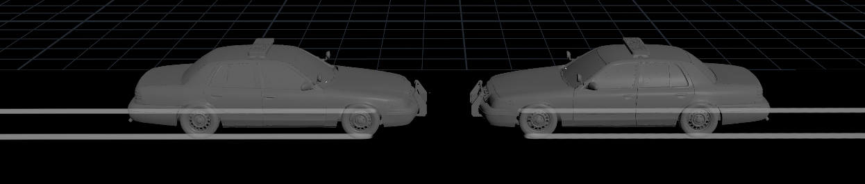
こちらのセットアップを使って車をアニメートしていきます。速度を設定し、キーフレームの操作やライブ入力によって車を操縦します。この後の衝突シミュレーションで使えるよう、Sim Points および、タイヤの拘束をキャッシュ化するのを忘れないでください。RBD Follow Path でパスに沿って走らせることもできますが、衝突シミュレーションでサスペンション用の拘束が必要になります。向かい合って走行するアニメーションには、2台に同じセットアップを使用できますが、その際、RBDXform を使って片方の車を反転させると良いでしょう。
ステップ 2.5 - カメラ
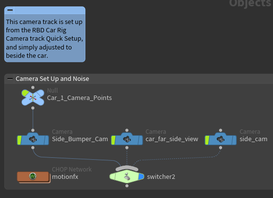
今度は、アニメーションで使用した RBD Car Rig のカメラトラック用セットアップを使って、より面白みのあるカメラのショットを作ります。メインカメラは、車の動きに追従する Side_Bumper_Cam です。3つのカメラを見ると、操縦席に設置された、車の動きをぴったりと追うカメラが1台あるので、それを選んで位置を編集し、左後輪の横まで移動させます。車へのトラッキングは、RBD Car Rig の Quick Setups ですでにセットアップされているので、これで準備完了です。
ステップ 3 - 車の破砕
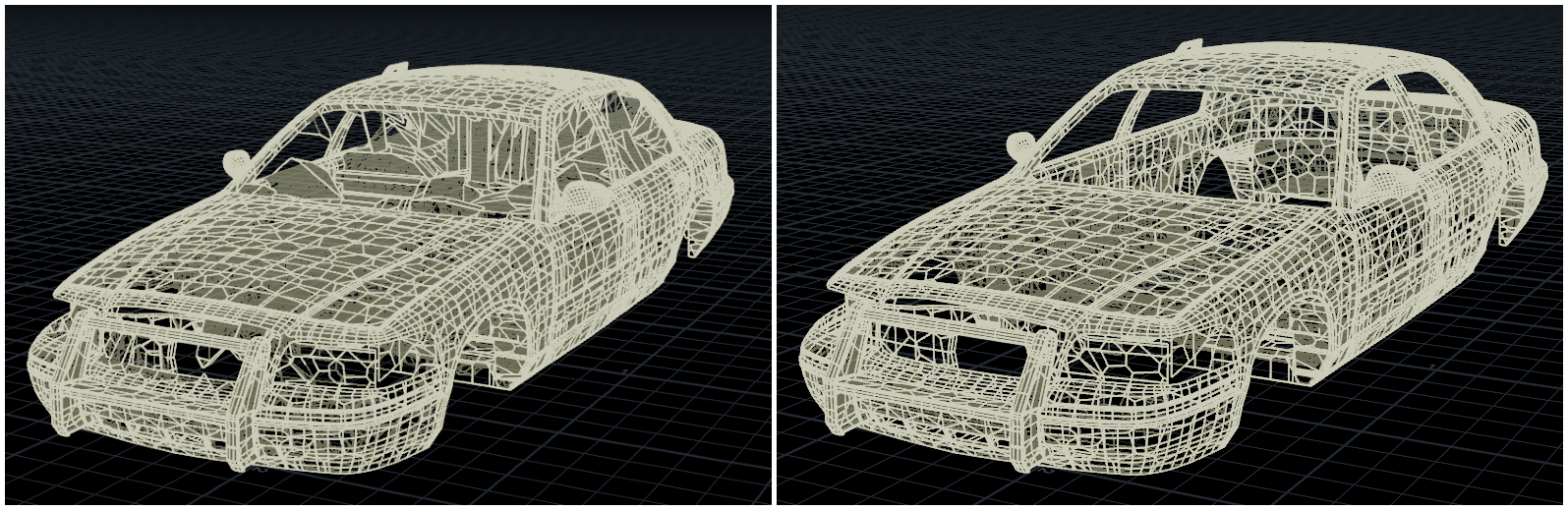
これで車のグループ化が完了し、RBD Sim で衝突を駆動させるのに使うアニメーションができました。次は、車の破砕を作成し、拘束と破壊表現の準備をしていきます。主要グループを順に確認し、金属ジオメトリをボロノイ破砕を使って破砕します。 Create Interior Surfaces パラメータのチェックを外してください。外さないと、ボディサーフェスの厚み不足で不自然なボロノイシェイプができてしまいます。ボディ、バンパー、窓といった主なオブジェクトグループのそれぞれで、この設定を行ってください。ただし、車内は壊れないので、ひとかたまりの大きなピースのままで構いません。(
破砕ピースの再構築
タイヤには破砕や破壊が発生しないので、RBD Car Rig からプロキシを引っ張ってきて、高解像度版のタイヤとそれぞれ一緒にパックするだでけでよいでしょう。全てのピースの破砕とキャッシュ化が済んだら、それらを集めて再び車の姿に組み立てます。
注
ピースの大きさは、適度なディテールが保てる程度に細かくしますが、小さくし過ぎないようにしてください。シミュレーションが極度に遅くなります。破砕後のオブジェクトにも引き続き問題なくマテリアルが適用できることを確認し、すべて万全であることを確認してください。
ステップ 4 - 拘束のセットアップ
破砕が完了したところで、全てのピースを結合させるための拘束を設定していきます。はじめに車の拘束システムを構築します。実際の車と同じく、ボディ/フレームなどの大きめのピースから構築していきます。パーツも全て統合し、しっかり固定する必要があるため、各セクションを1つずつ追加していきます。
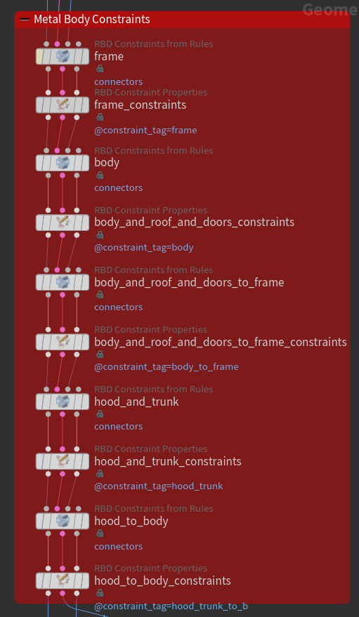
筆者が作成した、きれいに整理整頓されたネットワーク
SOP レベルの RBD Constraints from Rules ノードと RBD Constraint Properties ノードを使うと、破砕内および破砕間の拘束システムを手早く簡単に構築できます。変形する金属パーツは衝突まで Glue 拘束で結合し、その後 Constraint Switching を Soft に切り替え、衝突後は、ピース間がヒンジ状の繋がりを保ったまま変形したり曲がるようにします。
拘束グループ内の一部の拘束で調整が必要になるかもしれません。その場合は、拘束のストリームから該当箇所を切り離して強弱を編集してください。今回の例では、ボンネット、ワイパー、ガラス、エンジンの拘束で、より精確なルックにするための調整が必要です。終わったら再び統合し、念のため Geometry Spreadsheet を見て、変更が反映されていることを確認してください。
タイヤとサスペンションには、RBD Car Rig でによる拘束セットアップを使います。ただし、タイヤには、拘束の結合先となるプロキシボディが必要です。このプロキシボディは「body」と名付けてください。タイヤの拘束はこのオブジェクト名を検出し、それをネットワークに取り込んで、安定した中心点と結合するためです。ここでは、変形が生じず、車と同じ中心点を共有している車内を使うのが良いでしょう。車のモデルにシャーシがついていれば、それを使ってもよいですが、今回はついていないので、変形することのない車内部分が、強固な中心基盤となるため、固定先にするプロキシボディとして最適です。
注
- Soft 拘束と Glue 拘束の拘束値を決めるのに時間がかかることがありますが、ウェッジ化を繰り返し TOP を使えば割とすぐに適正値が見つかります。微調整が必要になる値は多くありますが、最も重要なのは、金属変形の度合いの決め手となる Soft 拘束に関する値です。
- ピース間の境界に沿って金属が折れ曲がるようにするため、結合のタイプには、必ず Hinges を選んでください。
- 同一ピースに複数の拘束は必要ありません。1ピースあたりの拘束数を抑えて、シミュレーションの重さを軽減しましょう。
ステップ 4.5 - RBD 設定と拘束の微調整
次は RBD Configure です。ここで各パーツの密度を調整し、シミュレーションをよりリアルなルックにしていきます。一部のピースにはプリセットを使用できますが、残りはシミュレーションに合わせて必要に応じて手動で調整します。また、一部のパーツにはクリーンアップをした後も相貫が残っており、車のルックを損ねるだけでなく、シミュレーションでも問題が起こります。そのため一部の衝突グループに、互いにぶつかるのを避けるための設定をして、シミュレーションの安定を保ちます。また、タイヤのプロキシボディも何かに衝突しないようにしましょう。このプロキシボディはタイヤを固定させるためだけのものなので、必ず、全ての衝突を無視させてください。最後に Active と Animated のパラメータを調整し、衝突の数フレーム前に実際のシミュレーションが有効になるようにします。
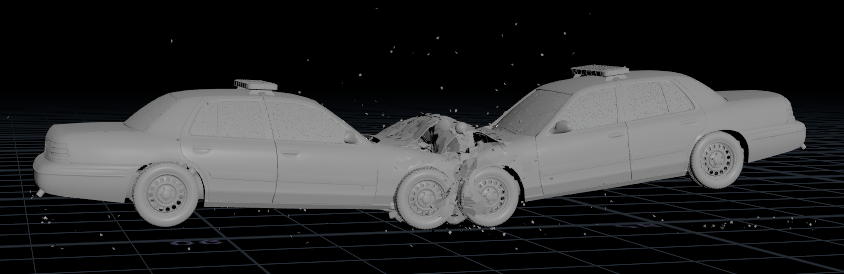
Active 化の瞬間を可視化したシーン
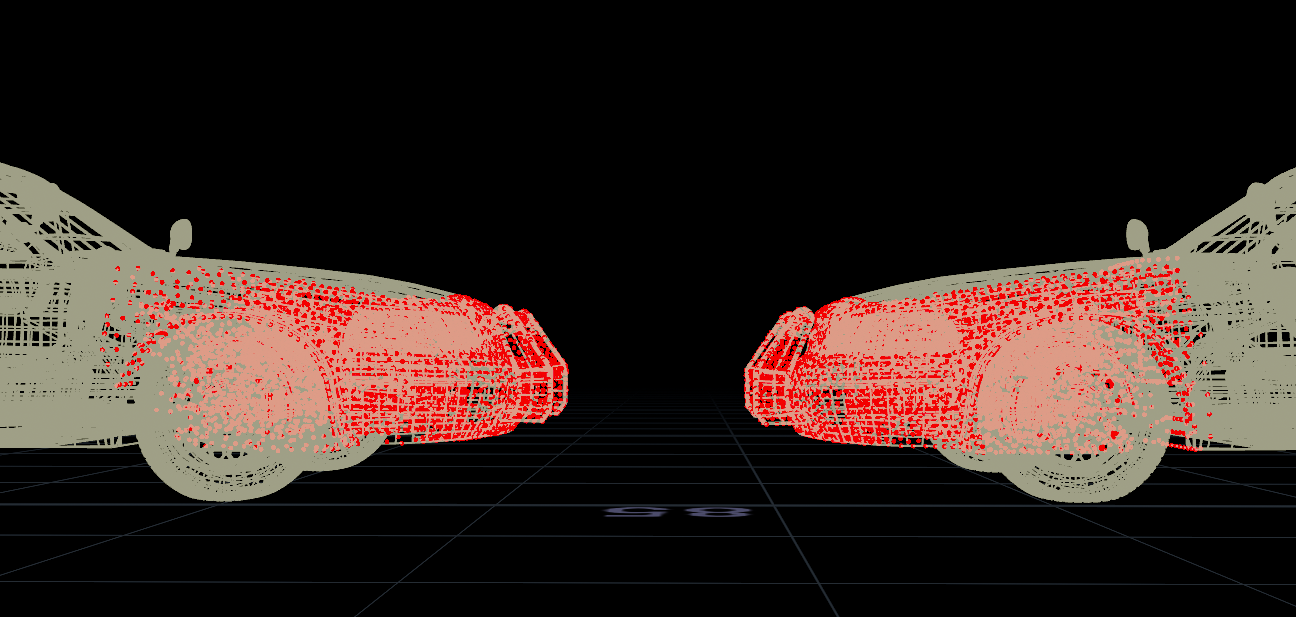
ここで、アニメーションと RBD Car Rig のタイヤ拘束を、破砕した車に転送します。こうることで、破砕の前後で運動量とタイヤの状態を同じに保つことができ、滑らかに繋がります。 RBD Car Rig シミュレーションのアニメーションの1フレーム目に合わせて2台の車をセットし、RBD Car Rig ノードから得られた結果と同じ名前にリネームします。ここでは「Body」 というピースと 「Wheel_Back/Front_Left/Right」という名前の4つのタイヤがそれです。その際、仮名称の @pname を使い、Transform Pieces で2台の車をトランスフォームして、元の名前が変更されないようにします。
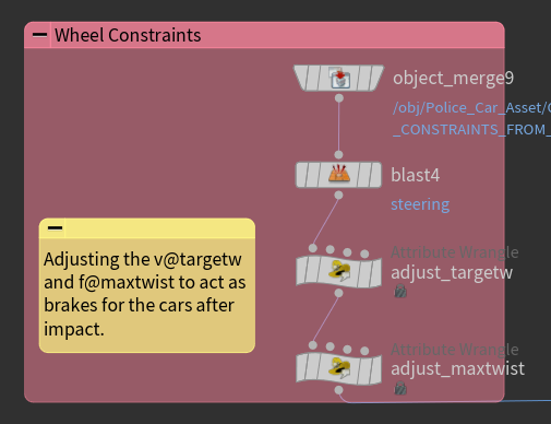
タイヤ拘束の編集用セットアップ
最後はタイヤの拘束です。調整や命名、トランスフォームは済んでいるので、先ほどの RBD Car Rig のキャッシュから直接、拘束のストリームにタイヤの拘束を流し込むだけで良いでしょう。シミュレーションの際にこれらの拘束を調整すれば、タイヤのモーターや挙動の制御も可能です。今回は、衝突した後の回転は必要ないので、ブレーキ役を果たす @targetw でモーターを減速させて回転をやめさせ、次に @maxtwist でタイヤを即座にロックして回転を完全に停止させます。それを実行するには、タイヤを「ロック」するフレームを選び、@targetw をゼロ、@maxtwist もゼロにします。これで、破砕アニメーションをつけた車と、そのアニメーションに合わせた拘束セットアップ、フル制御可能なタイヤの拘束が揃いました。
衝突には2台の車が必要なので、先ほどと同じセットアップでアニメーションを転送しますが、その際、2台めの車から転送するようにしてください。次に、RBD Pack ノードでパックします。RBD Unpack でアンパックする際は、Enforce Unique Name Attribute per Instance を有効にしましょう。これにより、各車の RBD ジオメトリに一意の接尾辞が追加され、拘束や RBD ジオメトリ内の重複を確実になくしてから、シミュレーションに入ることができます。
ステップ 5 - 衝突の完成
シミュレーションのセットアップはこれでほぼ完成したので、次に、安定性と拘束に関する一部の設定を微調整していきます。RBD BULLET SOLVER ノードを配置し、はじめに Bullet World Scale 値を上げ、一部の小さめのジオメトリピースを安定させます。サブステップの数については、ここでは Bullet Substeps を10にするとちょうど良いようです。値が高くなるほど、より不安定性になるため、このくらい低くする方が大幅に安定します。
変形のプロセスにも、Plasticity (可塑性) の代わりに拘束の切り替えを用います。衝突で Glue 拘束が離れ、Soft 拘束に切り替わると、ソルバは少しの間、Soft 拘束として振る舞うことを許しますが、その後、離れない Glue に戻して金属を変形させます。これは、RBD Bullet Solver の Constraint タブで簡単な VEX を記述するだけで設定可能です。
注
金属の変形に拘束の切替を使用していることで、衝突で変形した各車のパーツが、相手の車に入り込んで動かなくなる可能性があります。この場合、衝突グループに修正を加えて、特定のフレーム以降は互いを無視するよう設定し、車がぶつかり合わないようにすることで修正できます。切替フレームを選ぶ際に、若干手間どるかもしれません。
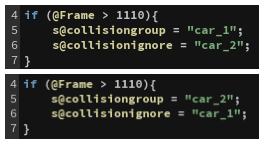
衝突グループと衝突を無視させるためのセットアップ
上流で調整をして、特定フレーム以降に変更を加えたのに伴い、シミュレーション内の重要なアトリビュートをいくつかオーバーライドする必要があります。Properties タブで、collisiongroup と collisionignore を追加して衝突の後に2台の車が離れるようにします。さらに、Constraints タブでオーバーライドしたアトリビュートにターゲットと max_twist を追加してタイヤを停止させます。これでようやく、シミュレーションを実行できます。
満足のいく最終ルックを得るには時間がかかるため、忍耐強くウェッジのセットアップを繰り返してルックを調整していってください。各パラメータで何ができるかのテストを積極的に行って、最終ルックにどのような影響を及ぼすか確認すると良いでしょう。各パラメータがシミュレーションに対してどのような影響を与えるか、しっかり理解しておくことは、非常に重要です。
ステップ 6 - ポスト処理
シミュレーションで得られたハイレゾは、ここで求めるものと完全に一致しないので、次のステップで元のモデルを変形させてシミュレートさせた RBD の車と一致させます。RBD シミュレーションで使用したプロキシジオメトリを使って、アニメートした破砕前の車を pointDeform させます。ただし、タイヤやガラス片はポイントデフォームさせないので、元のモデルから取り除いておきます。シミュレート後のハイレゾの方では逆に、タイヤやガラス片のみを残すようにします。pname を元モデルのポイントにプロモートするのを忘れないでください。ポイントデフォームでもこのアトリビュートが使用されます。
ビューポート
シミュレーションはショット中盤から実行されるため、前半部分のキャッシュが存在しません。ここでは衝突フレームまでキャッシュの代わりにアニメートした車のジオメトリを使い、その後、シミュレートしたジオメトリに切り替えます。そのため、ここでは、切替用のストリームをふたつ用意し、パーツ名を統一して、Solaris でより簡単にマテリアルを割り当てられるようにします。
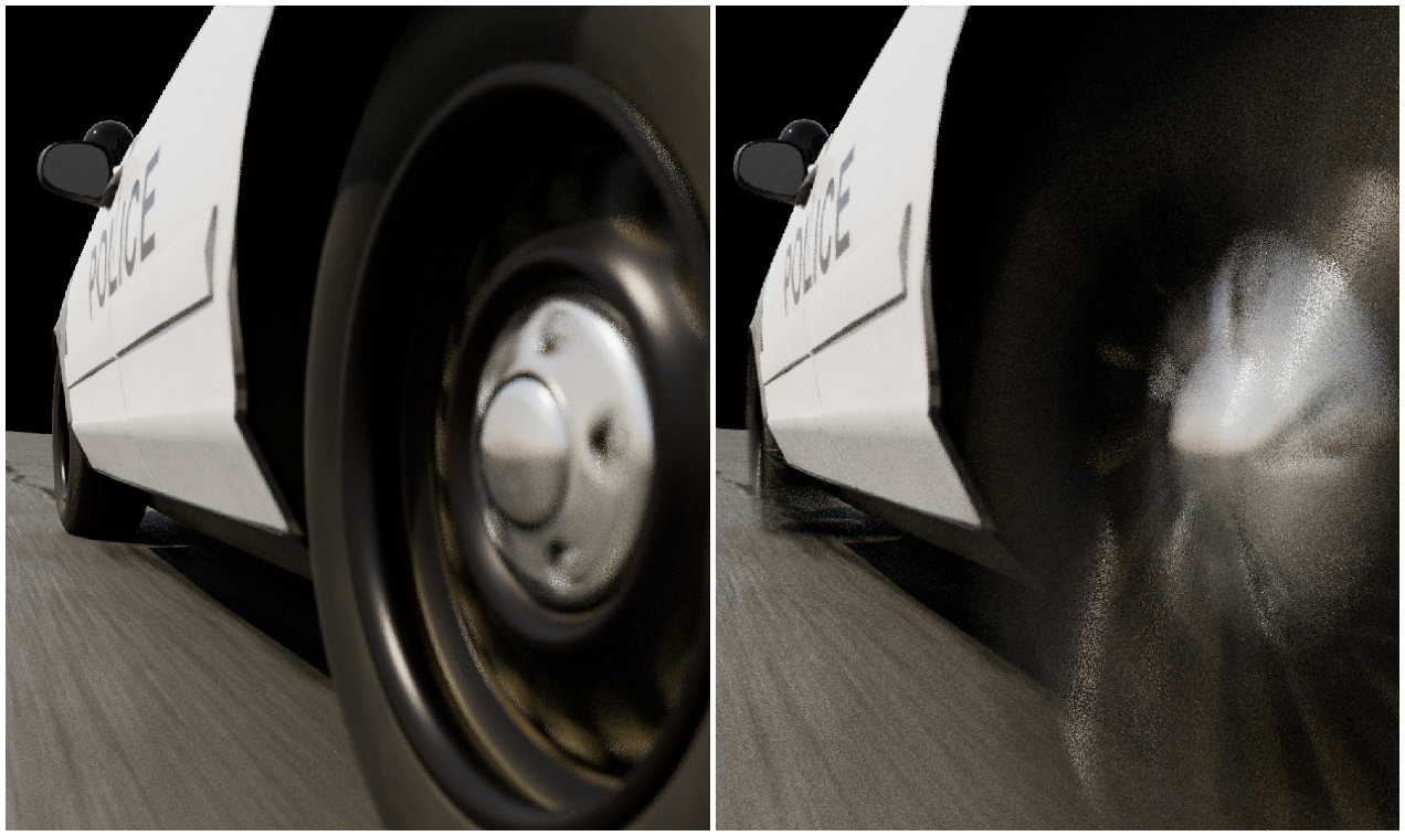
次に、RBDCarDeform ノードをセットアップしてタイヤに良い感じの潰しをつけていきます。それぞれの車に衝突の前用と変形用のノードを用意し、タイヤを選択します。これで、先ほどまでわずかに地面に相貫していたのが解消され、適切に変形するようになります。その方がよければ、やや下方向にトランスフォームさせ、道路との接地をよりリアルに表現してもよいでしょう。その場合、タイムシフトさせたタイヤを用意し、RBDCarDeform ノードでそのタイヤを選択するだけです。アニメートしたタイヤは、下方向に少しトランスフォームさせるだけで、変形後も接地感を保てます。
不要なデブリをいずれもクリーンアップし、Trail ノードを使ってモーションブラー用のベロシティを計算したら、Solaris に持ち込んだ時のための名称を設定します。このショットは、衝突の前と後との二部構成なので、衝突の1フレか2フレ前に2台の車を切り替えます。アニメーション駆動のシミュレーションのため、シームレスな切替が必要です。アニメートした元の車はアンパックして Name from Groups を実行し、Solaris で扱いやすくなるようにしてください。
モーションブラーに関するコツ
タイヤの Velocity と Angular Velocity がどちらも高いため、 Trail ノードでベロシティを計算するうえで重要な設定を有効にする必要があります。Velocity Approximation をデフォルトの Backwards Difference から Central Difference に切り替えてください。これにより、前のフレームだけだけでなく、前後のフレームとの差をチェックしたうえでベロシティが計算されるので、他のオプションのようにモーションブラーが不自然になることがありません。
ステップ 7 - 粉塵
メインの衝突が完了したので、セカンダリの追加に進みましょう。最初は Pyro シミュレーションによる粉塵です。粉塵をシミュレーションする前に、ラスタライズできるポイントが必要なため、変形後の車を選択し attribpaint を使って車両の前方 1/4 にポイントを散布します。衝突による影響を受ける唯一の領域は、バンパーからホイールウェルのすぐ後ろなので、そこにマスクをセットアップし、attribTransfer ノードを使ってこれらのポイントにベロシティ値を転送し、車の動きを少し乗せてやります。次に、それを POP Sim に流し込み、Pyro シミュレーションのソースとなるポイントを生成できるようにします。今回は衝突なので、Time Scale を高い数値から低い数値へとアニメートし、パーティクルがすばやく飛び出した後に急激に減速するようにして、煙が瞬時に広がりつつ、長く残るようにします。これで衝突にフォースが加わります。後ほど密度をラスタライズし、少し時間が経ったら消えるようにしたいので、@nage の 0 から 1 の値に合わせて @density と @pscaleを設定してください。
ポイントにベロシティノイズを加え、Disturbance (擾乱) /Turbulence (乱流) もつけて、粉塵の煙に若干メリハリをつけてルックを調整します。最後に車の VDB Collider が必要です。これにより、プロキシに対して VDBfromPolygons を適用し、それを Pyro シミュレーションに繋げられるようにします。
Pyro シミュレーションの最適化
ボクセルサイズを 0.007 にすると、シミュレーションがかなり重くなるため、pyrosolver 内の不要なフィールドを間引くのと、ポスト処理の設定を幾つか有効にするのを忘れないでください。Convert to VDB および Use 16bit Float は、必ず有効にしてシミュレーションの重さを軽減しましょう。また、Vel には Cull Mask Volume を使用します。これにより、シミュレーションのサイズを大幅に削減できます。
ステップ 8 - 道路用マスク
ステップ 9 - レンダリング
最終ステップは Karma、具体的には XPUによるレンダリングです。車、粉塵、パーティクル、道路をステージに持ち込み、マテリアルとライトを設定します。事前に名称設定したことで、マテリアルとオブジェクトを簡単にリンクできます。この車にはマテリアルが付属しているので、ガラスやセカンダリのマテリアル設定だけでよいでしょう。車には元のテクスチャのマテリアル、道路には提供されているマテリアルを適用し、ライトには Emissive マテリアルを設定して、ヘッドライトとテールライトに割り当てます。道路のマテリアルは、ネットワーク内に入って Switch を作成し、mtlxGeomPropColor ノードを使って取得したカラーアトリビュートによって切替を駆動します。これですべてにマテリアルを適用できたので、後はライトを追加してレンダーパスを設定すれば完了です。このチュートリアルが皆さんのお役に立つことを願っています。
CREATED BY

コメント
knockflakes 2 ヶ月 前 |
WOW! That`s amazing!!! Thank you so much for this great tutorial! And of course for the scene file! Once again, that`s amazing
MugoStudio 1 ヶ月, 1 週間 前 |
Great example! Can't wait to disect it with more simple vehicles.
moshvisuals 1 ヶ月 前 |
This is great!! <3 thanks
Tigran69199 3 週間, 5 日 前 |
Terrific job. Thanks for sharing this project))
Please log in to leave a comment.