| On this page |
Overview 
The ![]() RBD Car Rig SOP converts oriented car geometry into a driveable dynamic car rig with constraints for the suspension and motors. It is adaptable to any input geometry, and has 4 built-in wheel layouts (with a 5th option to customize the wheel layout entirely). The wheel and suspension properties can be set globally, per axle, or on individual wheels. You also have the ability to tune wheel camber, tire friction and bounciness, suspension travel, stiffness, and damping.
RBD Car Rig SOP converts oriented car geometry into a driveable dynamic car rig with constraints for the suspension and motors. It is adaptable to any input geometry, and has 4 built-in wheel layouts (with a 5th option to customize the wheel layout entirely). The wheel and suspension properties can be set globally, per axle, or on individual wheels. You also have the ability to tune wheel camber, tire friction and bounciness, suspension travel, stiffness, and damping.
Car geometry 
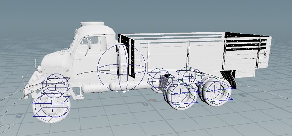
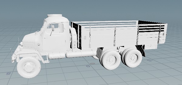
You can use your own car geometry, or you can download a truck FBX file from the Content Library. Using this with the ![]() RBD Car Rig SOP in Houdini lets you turn it into a drivable RBD vehicle. In this explanation we will be using the truck geometry, but the methods can be applied to any vehicle.
RBD Car Rig SOP in Houdini lets you turn it into a drivable RBD vehicle. In this explanation we will be using the truck geometry, but the methods can be applied to any vehicle.

Setting up the rig 
-
Import the truck FBX file from the Content Library, or use your own car.
-
Connect it to the input of the
 RBD Car Rig SOP.
 -
Select the Wheels Group and the Wheel Layout.
For the demo truck, you can use
@wheels=1for the Wheels Group and 3 Axles for the Wheel Layout.Note
If you choose a different wheel layout, such as 4 Wheels for the 3 axle truck, it will group the back wheels as two big wheels instead of 4 small ones.
Tip
If you have more wheels, you can choose Custom and in the Wheels section click the plus button to manually add the number of wheels you have. You can then set up each wheel individually by assigning it to a wheel group, choosing whether it’s Front, Back, Left, Right etc.
-
Set an optional Steering Wheel Group.
The demo truck doesn’t have a steering wheel, but if you have one this parameter will automatically rotate the steering wheel geometry according to the steering inputs, without contributing to the RBD simulation.
-
Select any geometry to ignore when generating the car body’s proxy collision geometry. Typically this would include antennas, which might protrude and alter the overall volume of the car body in a significant way.
-
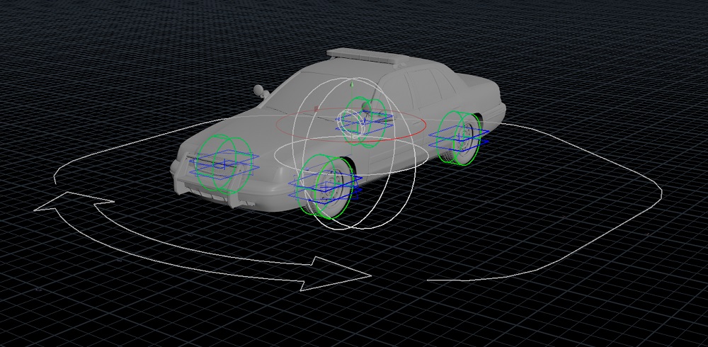
Set the Drive Mode to specify if the car is Front Wheel Drive, Rear Wheel Drive, or 4×4. For this demo, we are using Front Wheel Drive, which are represented by the green visualizer. This will determine where the motors are attached when driving the car.
Outputs 
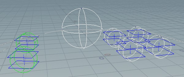
The first output is the high-res geometry (original geometry), packed into packed primitives based on the wheel selection. In this case there are 7: one for each of 6 the wheels and one for the body of the truck.
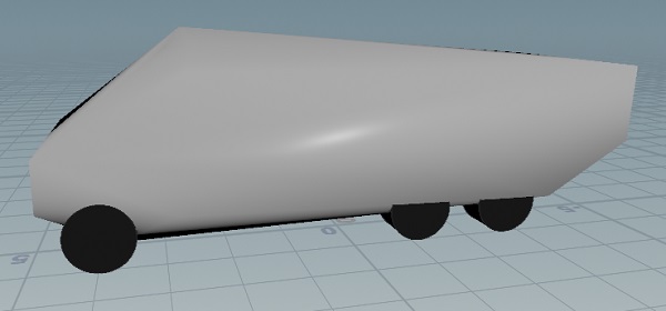
The third output is the proxy geometry. In this case you will have 6 tubes, one for each of the wheels, and 1 packed primitive for the rest of the body wrapped in a convex hull.
Note
These are equivalent to the high-res and low-res geometry you would have with RBD Material Fracture.
The middle output is the constraints, which you don’t have to set up with manually since this node sets up constraints that will control rotation of the wheels (steering) and suspension (moving up an down).
Configuring the rig 
| To... | Do this |
|---|---|
|
Display the original high resolution geometry |
Turn on the Show Geometry checkbox. |
|
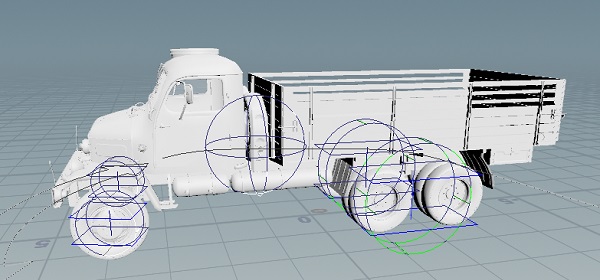
Display the rig guides |
Turn on the Show Guides checkbox. |
|
Display the proxy geometry |
Turn on the Show Body Proxy Geo checkbox. |
|
Change the center of mass of the vehicle |
Use the Center of Mass parameters or the handles in the viewer state to change where the center of mass is along the height and length of the vehicle. For example, the front of the truck is usually heavier than the empty truck bed, since that’s where the engine is. Moving the center of mass slightly toward the front would make it behave more realistically. Tip A higher center of mass will allow the truck to roll over in turns, while a lower center of mass will help prevent that from happening. |
|
Improve cornering behavior for the vehicle |
Increase the Ackermann Steering Angle. When this is set at 0, both wheels will turn exactly the same amount. As this is increased, the outer wheel will turn less compared to the inner wheel. This helps improve cornering behavior since the two wheels travel different distances around the arch.
|
|
Create a bouncy/springy suspension |
Increase the Travel parameter and decrease the Stiffness and Damping parameters in the Suspension section. Travel controls the range in which the suspension can move up and down, and the stiffness and damping control the rigidity of the suspension. |
|
Prevent slippage when driving |
Change the Differential to Locked or Limited Slip in the Motors section. |
|
Create a slight compression on the tire where it touches the ground |
Decrease the Wheel Scale parameter to make the wheel’s proxy geometry slightly smaller than the |
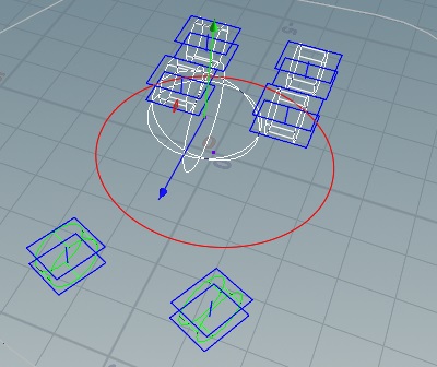 Ackermann Steering Angle of 0.
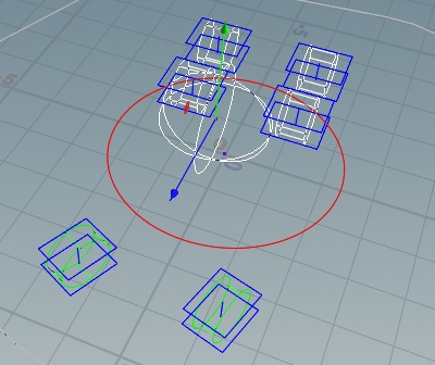 Ackermann Steering Angle of 0.75.
Driving the rig 
The RBD Car Rig tool has a viewer state with controls for driving the car. There is also a visualization of the current speed of the vehicle, as well as the Drive Mode.
W - Accelerate
S - Decelerate
A - Turn left
D - Turn right
E - Brake
G - Hand brake
Pressing these keys will cause the amounts to increase/decrease by fractional amounts, according to the Acceleration Profile ramp on the Configure tab.
Note
If you have a game controller or a steering wheel, you can use the ![]() Game Pad CHOP to override the driving parameter controls.
Game Pad CHOP to override the driving parameter controls.
| To... | Do this |
|---|---|
|
Use the view state keys to record a driving session |
Keyframes will be added as you use the controls. |
|
Change the unit of speed |
Use the dropdown menu beside the Speed parameter to choose between km/h and mph. |
|
Display the guide geometry for the wheels in the viewer state |
Turn on the HUD Scale parameter. This will give you a visual representation of the steering and braking happening on the wheels, as well as an indicator of the Drive Mode you're using. |
Next steps 
After setting up the car rig, you can use the Quick Setups dropdown menu to add the: RBD Solver and Add Cameras.
RBD Solver option 
The RBD Solver option will create a few nodes in your network. It will add an RBD Transform node that will allow you to move the starting position in the car easily, without having to do it upstream. This is then wired into an ![]() RBD Bullet Solver. The solver provides a quick way to add a ground plane as well as opens up some additional Properties, which are used by the
RBD Bullet Solver. The solver provides a quick way to add a ground plane as well as opens up some additional Properties, which are used by the ![]() RBD Car Deformer. For more information, see Using RBD Car Deform.
RBD Car Deformer. For more information, see Using RBD Car Deform.
It also sets up attributes for tracking cameras. You can add cameras with the Add Cameras option in the Quick Setups menu.
Add Cameras option 
This option adds 3 cameras to the scene that are connected to the camera tracking attributes. You can choose between BirdsEye (top-down view), Cinematic, or Cockpit (view from behind the steering wheel).
Dynamic Follow Path option 
This option adds an ![]() RBD Car Follow Path SOP, which shows you a preview at the SOP level of what the motion will be. All of the parameters are channel referenced with the DOP level
RBD Car Follow Path SOP, which shows you a preview at the SOP level of what the motion will be. All of the parameters are channel referenced with the DOP level ![]() RBD Car Follow Path node. This allows you to do almost all of the parameter tweaking at the SOP level. You only need to dive into the DOP if you want to edit any of the dynamics specific parameters.
RBD Car Follow Path node. This allows you to do almost all of the parameter tweaking at the SOP level. You only need to dive into the DOP if you want to edit any of the dynamics specific parameters.
Simply wire your curve into the fourth input of the ![]() RBD Car Follow Path node. You can then use the Curve Position parameter to keyframe points along the curve to control how the car moves along it. It will animate between 0 to 1 along the length of the curve, which represents the frame range.
RBD Car Follow Path node. You can then use the Curve Position parameter to keyframe points along the curve to control how the car moves along it. It will animate between 0 to 1 along the length of the curve, which represents the frame range.
For more information, see Using RBD Car Follow Path.