F1 Simulator Track Modelling – Barrier Generation
Q3D Studios is a small 3D visualisation studio in the UK that operates within the Motorsport and Automotive industries. For over 20 years, they have worked closely with a Formula One team in the development of Digital-Twins of real racetracks for their Racing Simulator. In this article George Pennyfather, Technical Artist at Q3D Studios, discusses one area of their procedural track pipeline – The Barriers.
The Motorsport industry is one that demands constant innovation, and speed in all departments. Simulation is no exception to this, and as such, the team at Q3D Studios is committed to continually accelerating the efficiency of our 3D pipelines, and find Houdini to be the best software for achieving this goal.
It’s easy to think that race tracks never change, but all tracks, and especially street circuits, are in fact constantly evolving. As such, we have to regenerate large amounts of procedural geometry before every race. Barriers, especially the manually placed “Temporary Concrete” ones, are particularly prone to change. So, with Houdini’s high ceiling for pipeline automation (which we are still far from reaching) we recently focused on renovating our barrier generation pipeline.
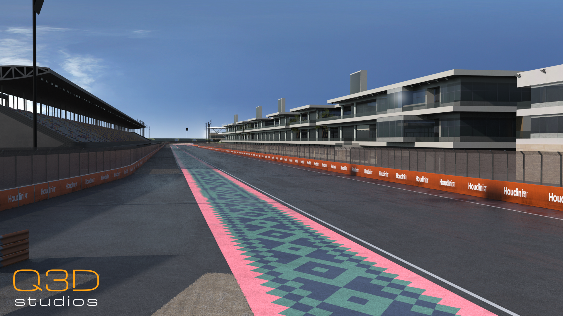
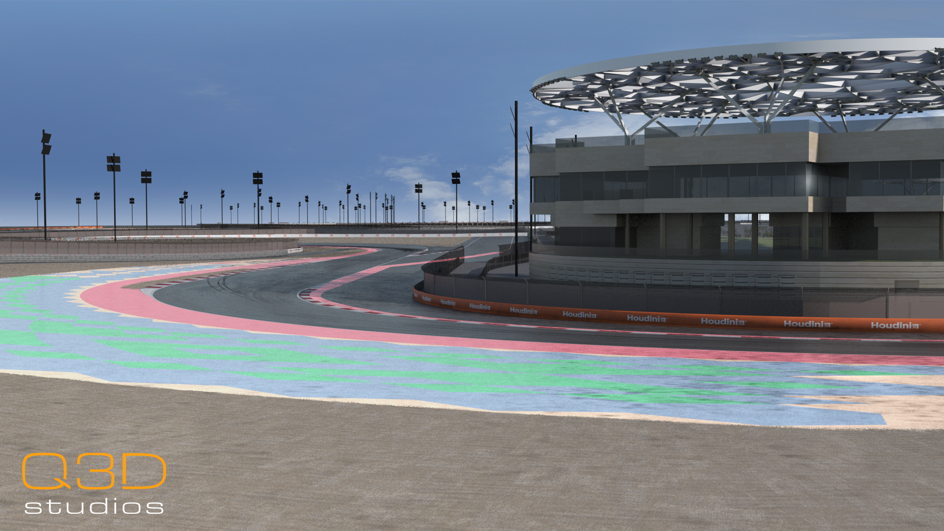
Figure 1 Simulator Track for the Lusail International Circuit in Qatar
Historically, we would have relied on nodes with heavy user-input, like curves and attribute paints, to manually trace barrier positions from LiDAR and paint advertisement attributes onto the splines. This was arduous and unstable, with frequent restarts upon adjustment to any barrier splines. Therefore, the focus of our new pipeline was to reduce time taken to trace barriers and improve the stability of advert placement when updating the input.
Barry - Our Solution to Tracing Barriers
When producing a simulator track model, we often acquire a full LiDAR scan of the race circuit. This is filled with valuable data that allows for maximum accuracy, which we believe is essential to delivering the best possible F1 simulator track models. However, taking full advantage of this is an intricate and time-consuming process.
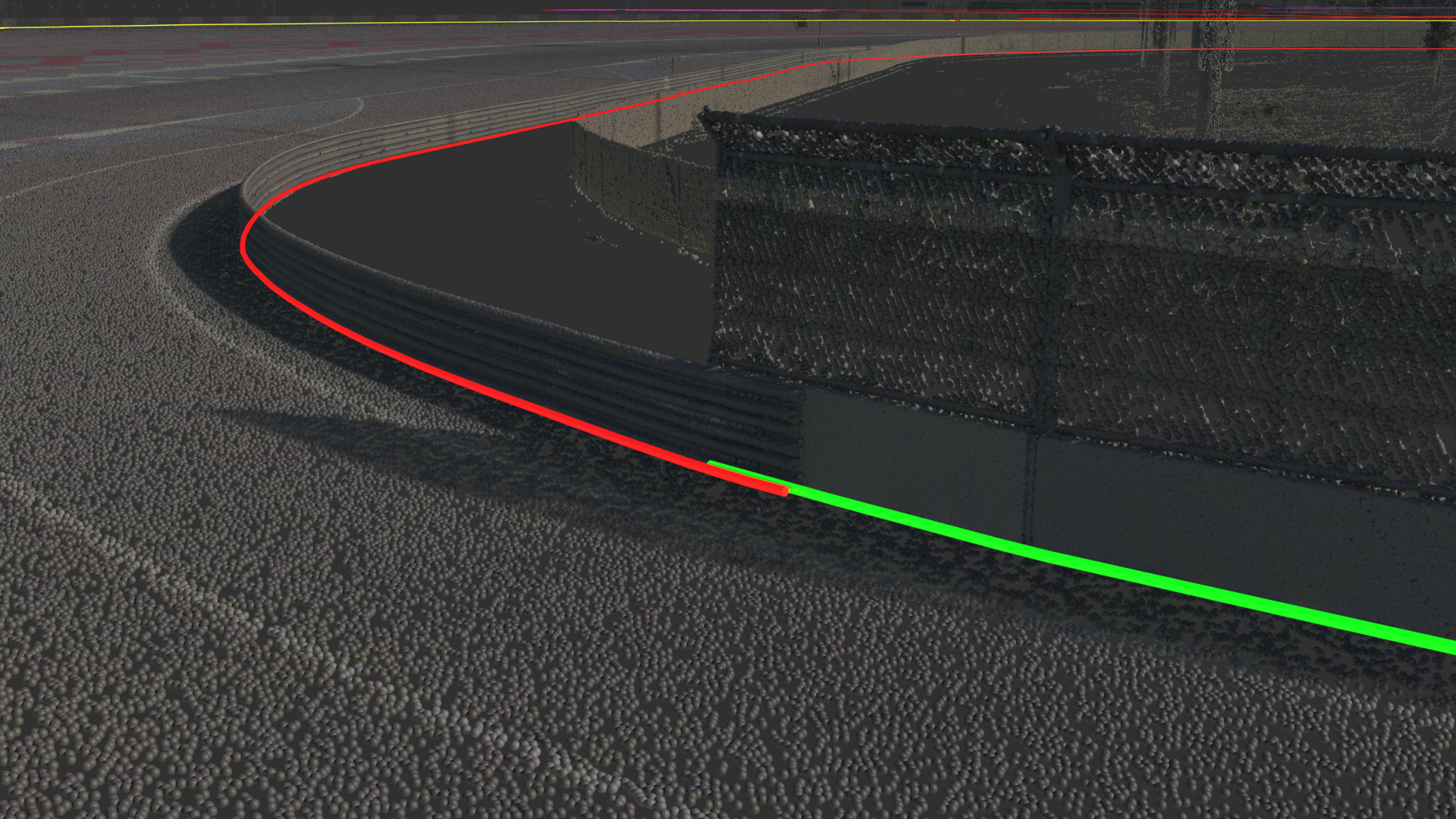
Figure 2 Lidar with traced splines
At all stages of our pipeline, we ask ourselves “How can we save clicks?”. Clicking takes time, and time is often in short supply. So, spending multiple days manually tracing out the exact positions of barriers from LiDAR is inefficient. To optimise this process, we produced ‘Barry’, a handy little VEX-powered tool that helps trace out the front faces of barriers. Barry does all of the clicking for us, moving from a start position to accurately draw a spline along the edge of a point cloud. Bots can be placed by clicking in the viewport, so this reduces the process of tracing splines to just roughly drawing the first point, saving significant time (and clicks).
The only additional step added by using this pipeline involves how we process point clouds. Barry traces barriers from flattened point clouds, and therefore our first step when using him is to isolate non-ground surfaces (we currently use Cloud Compare). After flattening, this leaves us with blobs of points that represent all of the barriers, buildings, foliage etc. This process is easily done, and is a small price to pay for how efficient Barry is compared to manual tracing.
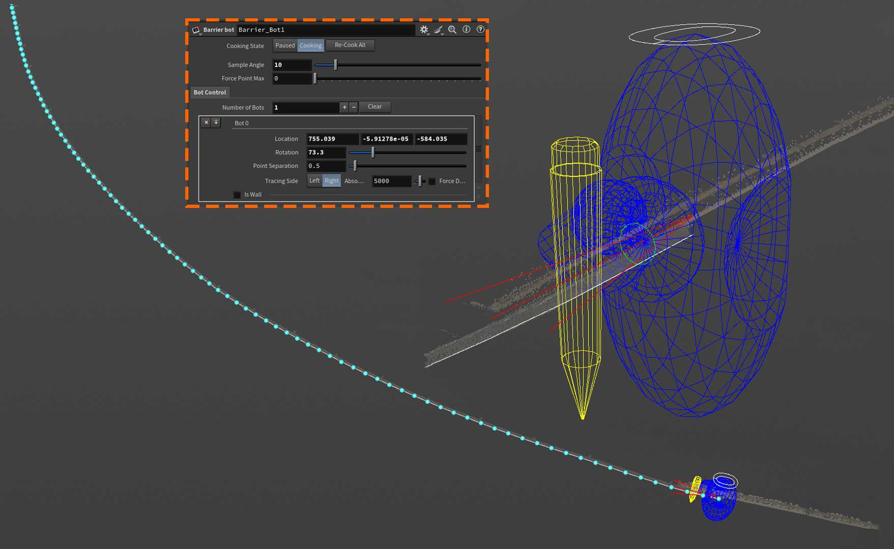
Figure 3 Barry placed on a barrier, tracing a spline. Example of the Barrier Bot UI.
For a more in-depth breakdown of the logic behind Barry, and their more sophisticated cousin ‘Tracey’, watch our HIVE talk that we gave at Everything Procedural Conference 2024 on procedurally processing LiDAR data.
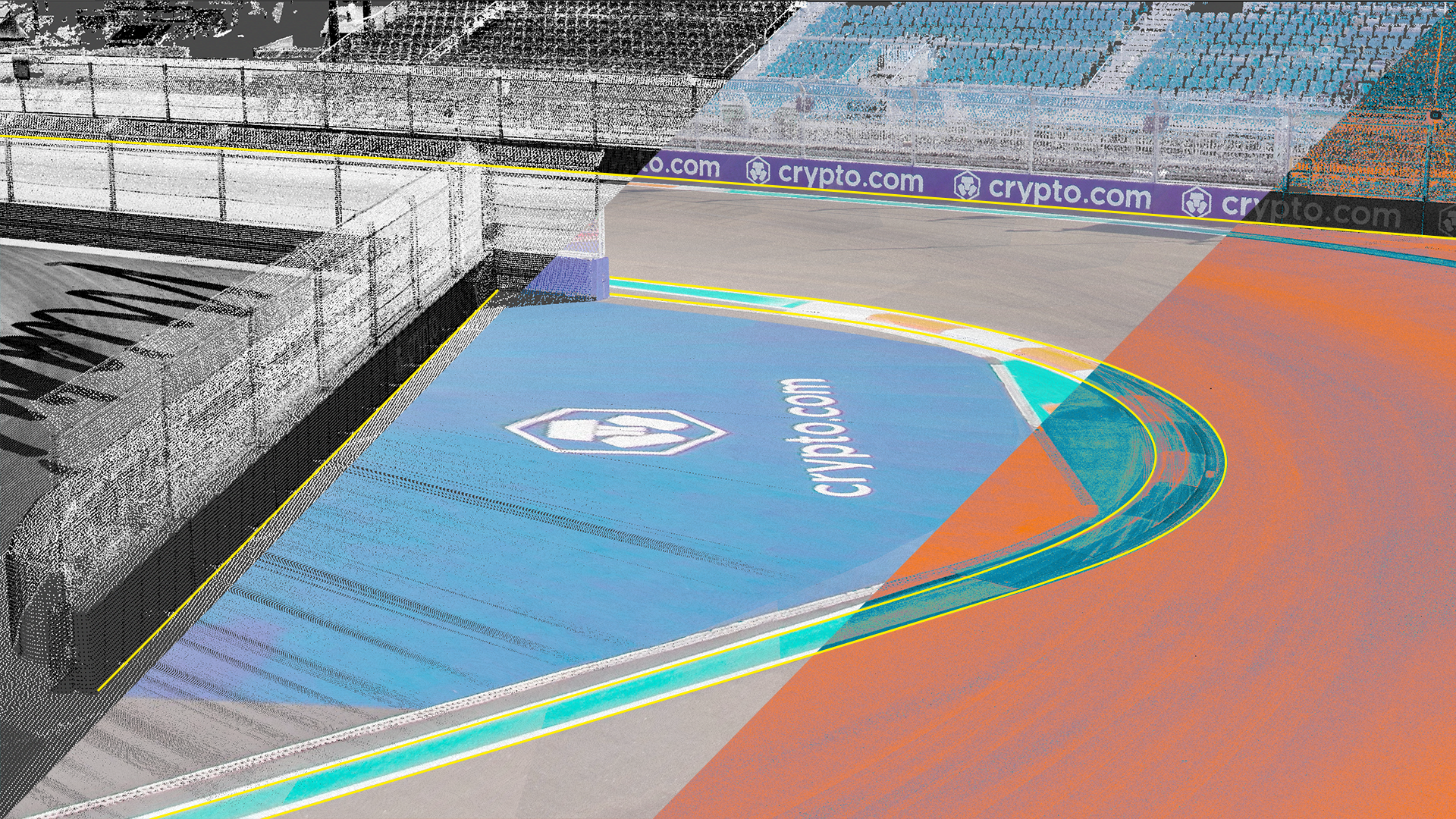
Figure 4 Lidar to Level – Andy Footman & George Pennyfather - EPC 2024
Barrier Painting
Once the splines have been drawn out, we need to define which advertisements are displayed on the barrier geometry. F1 circuits are always covered in advertising, and it’s important for us to replicate this in our digital twin to help emulate the atmosphere and orient the drivers. Importantly, we must ensure no logos are cut in half, which is jarring and unrealistic.
We can only use our own team’s sponsors for advertising boards, so in this article we have replaced them for anonymity.
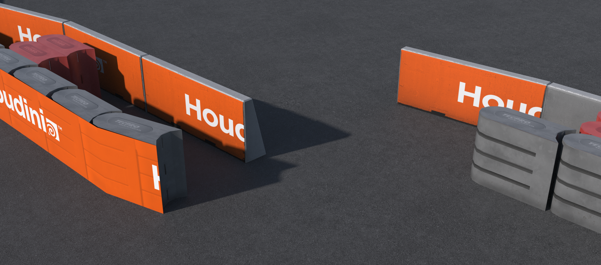
Figure 5 Incorrectly Formed Barriers. Logos are cut in half, and are displayed on walls occluded by other barriers.
As mentioned previously, attribute paints were used to paint and refine a “Material_ID” attribute on the splines. This could take a whole day to get right, and would require continual adjustment and repainting whenever the input splines were tweaked.
To resolve this problem, our new pipeline combines a volume-based approach for prescribing ads; with a system that uses Python and VEX to measure UV positions and calculate if any logos have even a single pixel cropped.
The Process
1 | Volumes are drawn and formatted using a bespoke HDA, which ensures all splines are constructed correctly and have a material attribute applied. ‘Orange End’ volumes are also generated at the end of splines. Orange ends are used in racing to signal breaks in the barriers large enough for a car to be removed through, in the event of an incident.
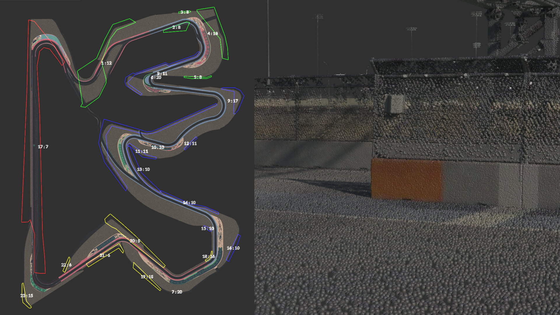
Figure 6 Formatted Advertising Volumes (Left); Example of an ‘Orange End’, captured in Lusail LiDAR data (Right)
2 | These volumes, plus relevant barrier splines, are plugged into the assignment HDA. If the barrier is situated behind another (figure 5), you can input this as an optional “Occlusion Spline”, which will strip adverts from this area.
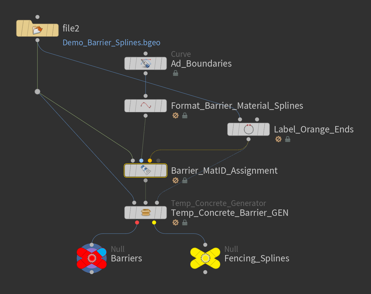
Figure 7 Network Architecture
Temporary Concrete geometry has a fixed width, and splines are rarely a length that perfectly divides into this width. As such, Dynamic Resample goes through three sequential passes, testing and adjusting the spline from best-to-worst case. The best case with a resampled spline is to resample with even segment lengths, slightly increasing the gaps between each barrier to make up for any excess space within the spline. For example, if you had a 100m spline, and needed to fit 3m barriers on it, a small amount of space can be added between each barrier to make up for the 1 metre excess on the spline without causing much visual difference.
There are unfortunately many instances where the spline cannot accommodate this, and using this method would force geometry to overlap or create unrealistic gaps in the barriers. In this case, the first point of the barrier is extended outwards to allow the spline to be resampled safely. However, if there are two barriers that meet each other at a right-angle, extending one of them out will cause them to overlap in an unrealistic way. To address this, the final pass checks for intersections and truncates the spline to fit the gap again. At later stages a small barrier piece can be generated to match the trimmed section of spline.
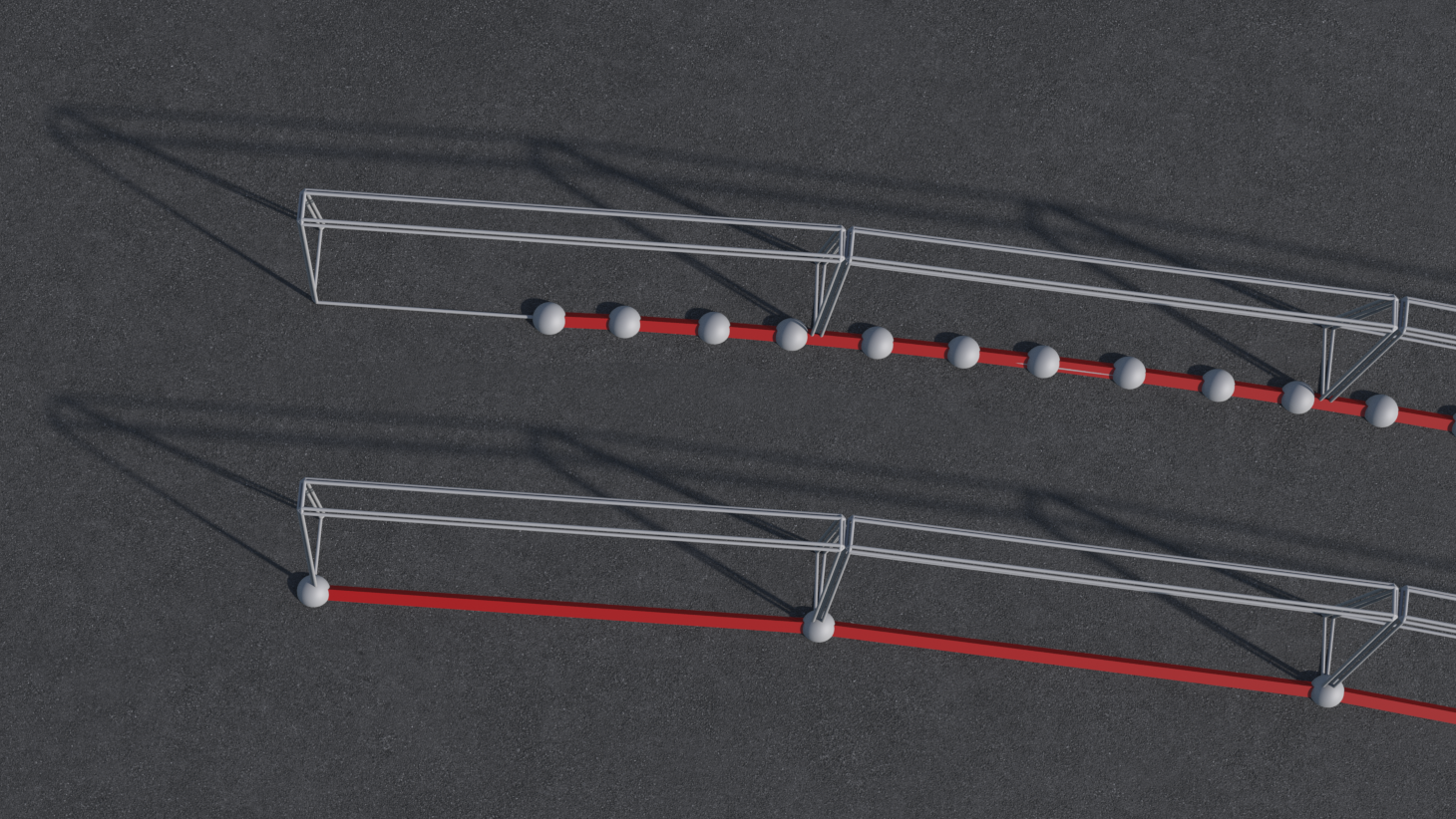
Figure 8 Demonstration of how a spline is dynamically extended so that it can fit all necessary barriers.
4 | Initial material IDs are applied to all points captured within the material volumes. The occlusion splines then produce their own volumes to define points that require an ad-free concrete texture. This will be very rough at this point, and likely filled with overlapping and cropped advertisements.
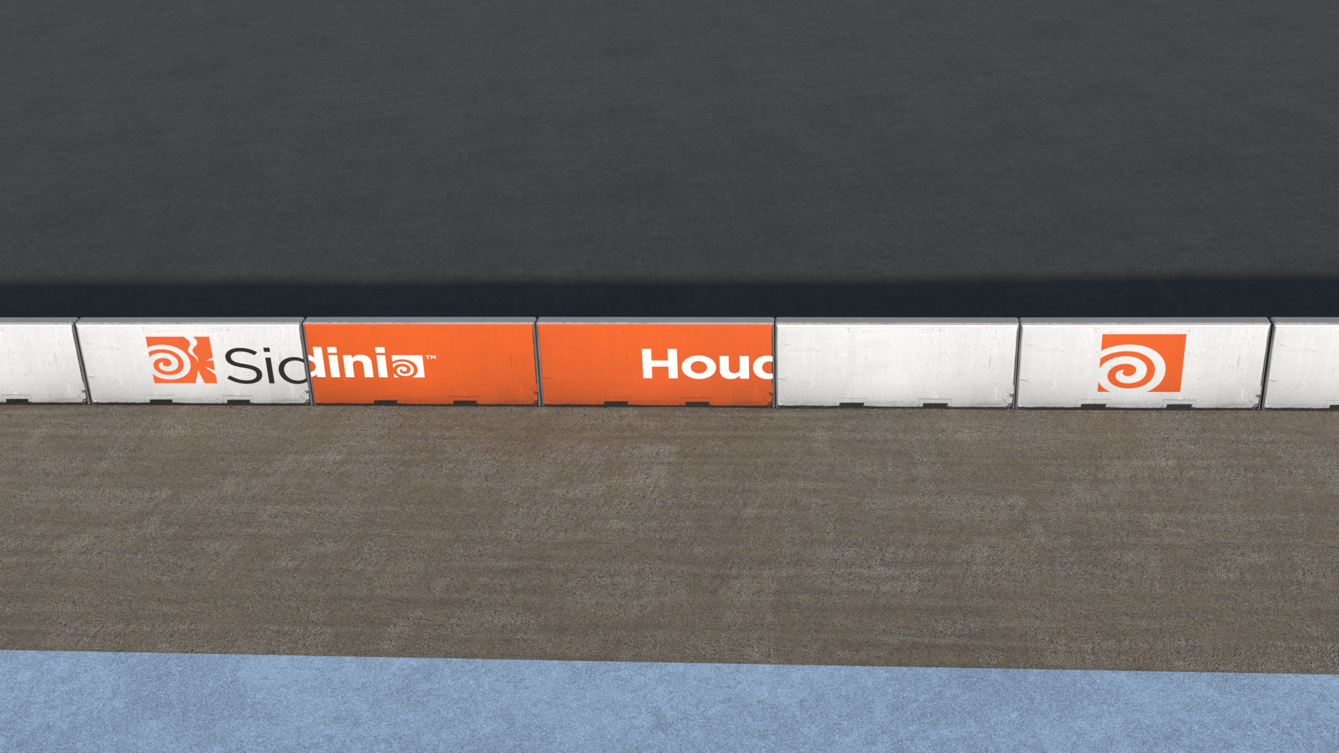
Figure 9 Results of constructing a barrier from unprocessed MatID splines
5 | A sweep is then used to produce a proxy mesh for testing UV values. This testing is done in two passes, one that tests seams produced by the orange end volumes, and another testing the seams between advert types or the end of a barrier.
In each case, the seam is tested in UV space to see if it falls within an “Unsafe” range, which is defined in an external text document. By measuring the pixels of the logos in photoshop, we produce a document that contains lines defining areas of the 0-1 UV space that contain a logo.
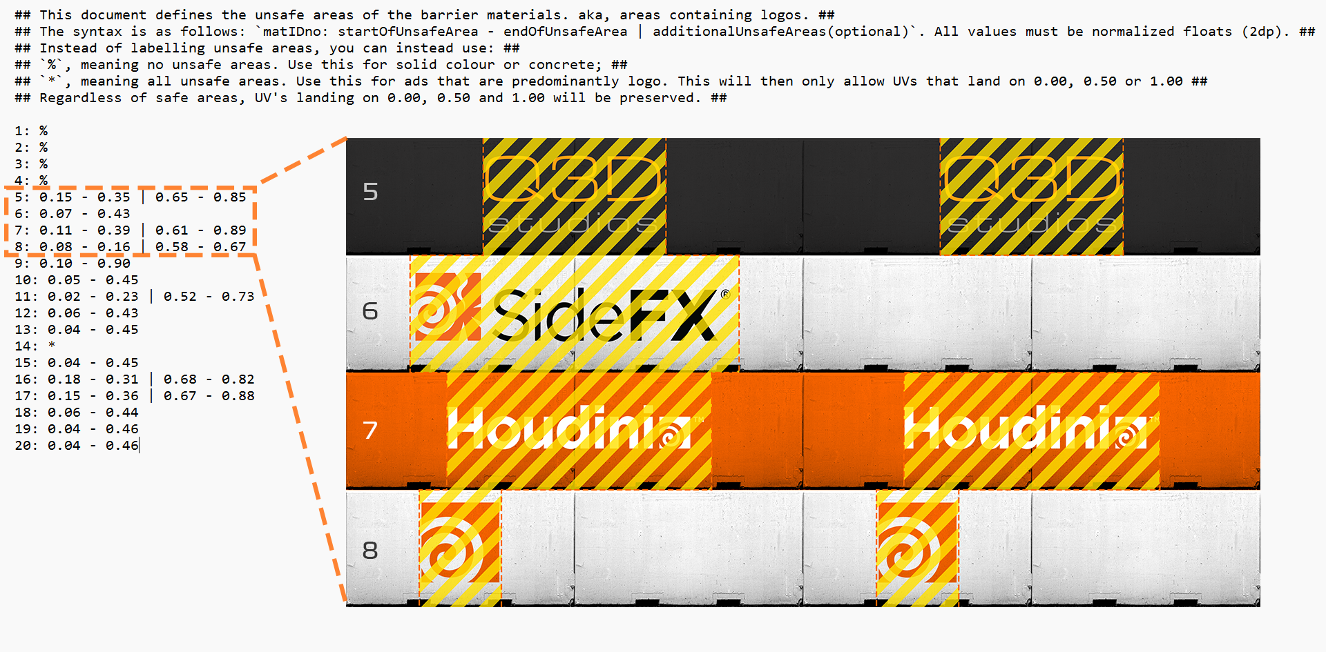
Figure 10 Example of a text document outlining where logos lie in UV space
A Python node in Houdini opens and reads this file, inserting each line into a string array detail attribute. The array is then translated in VEX into float ranges, which are compared to the ‘U’ values of the proxy mesh to identify if any seams fall between these areas.
In the event of a seam intersecting a logo, the material assignment will overwrite the advert onto the subsequent barrier piece so that it no longer clips (provided that this doesn’t crop the next advert). If there is no available option to fix the cropping, that area of advertisement is stripped to bare concrete.
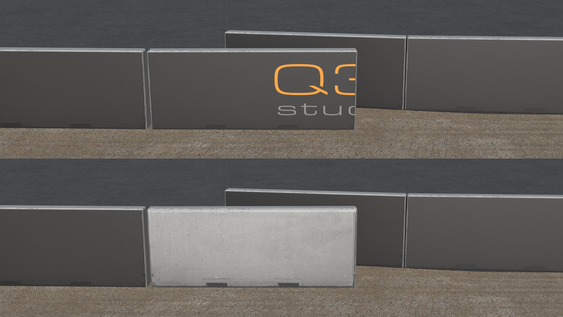
Figure 11 Bisected logos at the end of barriers are automatically stripped
The Outcome
Through this process, we are now able to produce clean, accurate adverts in a way that is efficient and robust. Should we adjust a barrier location, it will automatically regenerate the paint splines so that the ads stay clean, with no need for manual input. Volumes can be roughly placed and assigned to whatever advertisement is necessary for that year, and this node will handle all of the cleanup automatically.
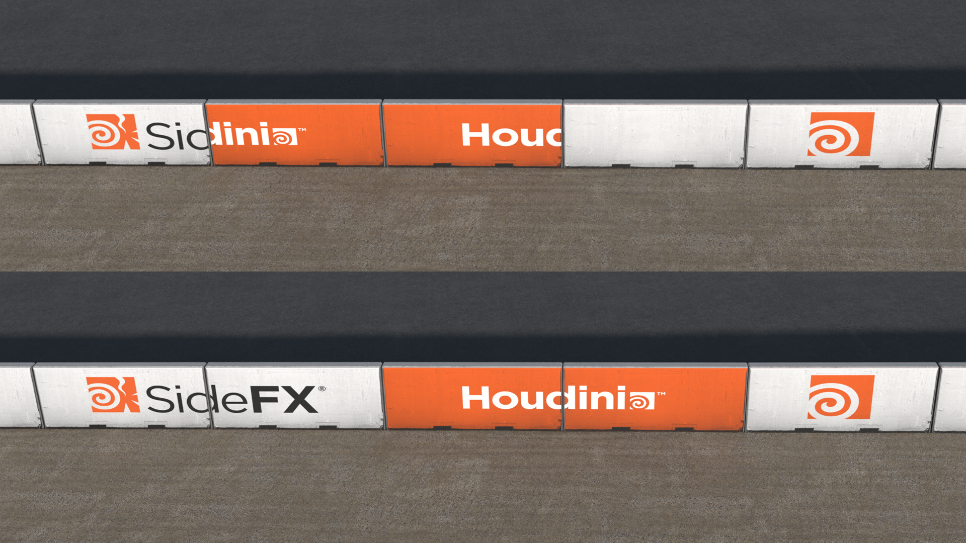
Figure 12 Clipped barriers are automatically offset to clearly display their logos
The high locational accuracy of this node allows for greater control over the barrier visuals as well. We can place painted orange volumes on logo-free areas without disturbing the materials, and if a logo is small enough, we can fit an orange area around the logo. Since the seams of the orange area technically fall outside of the logo’s UV range, no clipping is registered and thus the background colour is preserved. It is only when one or more seams directly intersect with a logo that the barrier is switched to plain concrete.
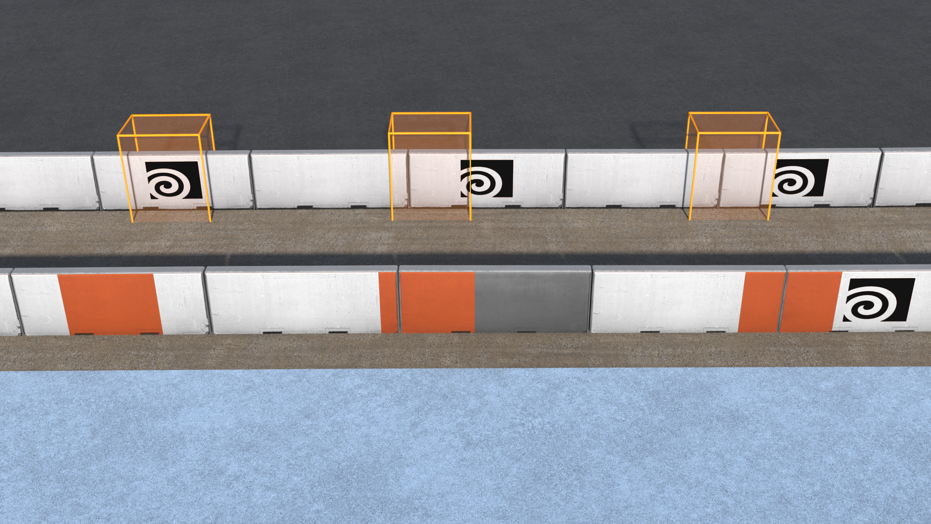
Figure 13 Demonstration of how Logos and Orange Volumes interact
To produce more visual variation in the final barriers, a random Material ID is assigned to all ad-free areas, which represents different variations of plain concrete.
At this stage, we have produced a spline that represents barriers with their assigned advert/concrete using a material ID point attribute. This keeps the cook time of the node incredibly low, allowing us to adjust and update in real-time.
Geometry Generation
With a lot of the more complicated processes now complete, all that’s left is to generate the final barriers using these splines and orange end volumes.
1 | A single barrier piece is generated to be copied to the input curve. We usually use a low poly version of the barrier for optimisation purposes, but we do have the option of producing high-poly variations. These include edge wear, noise and randomized vertex colours for different use cases.
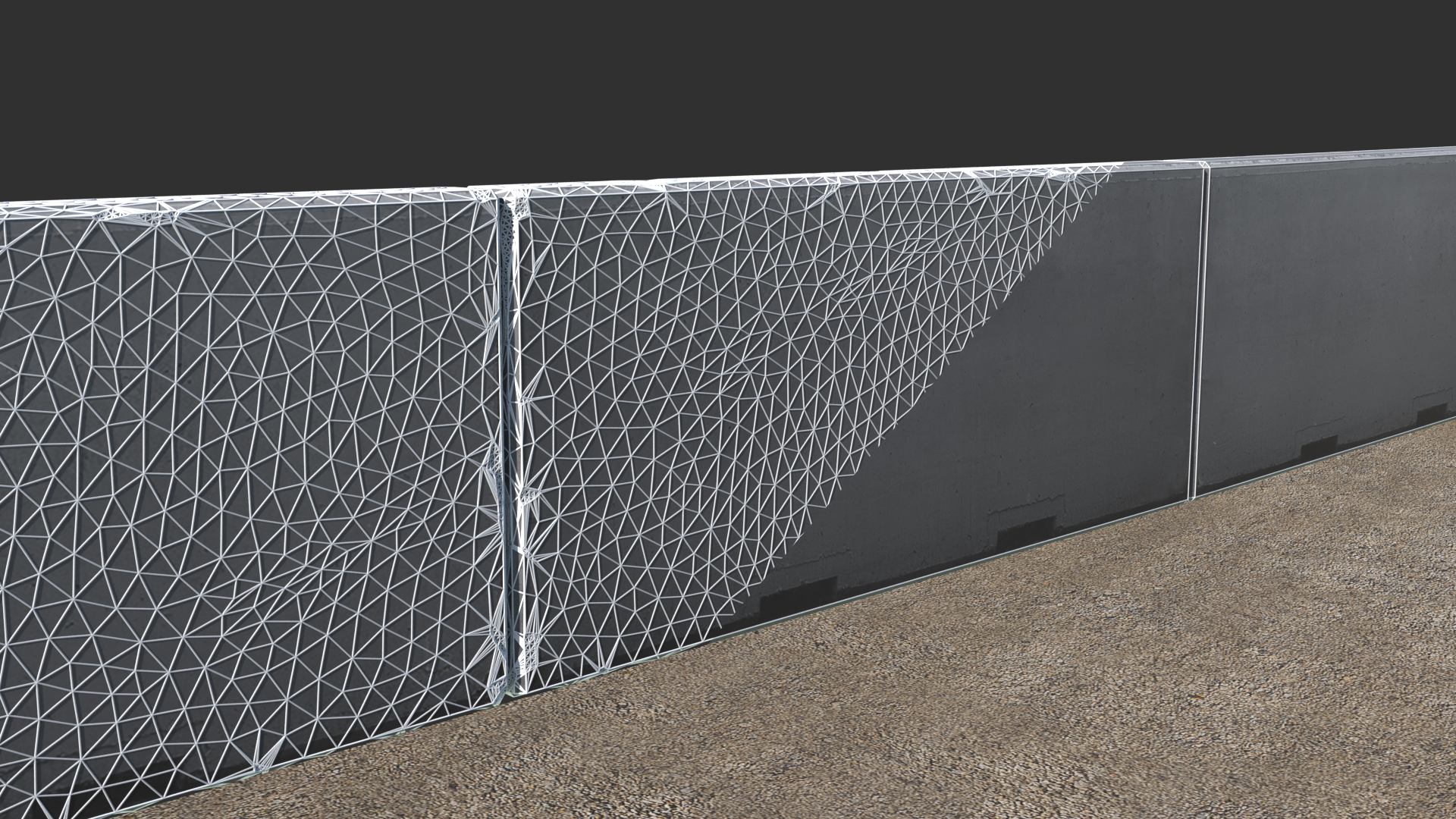
Figure 14 Side-by-side comparison of high-low barrier geometry
2 | This is then transferred to a spline that has undergone the same resampling process as was used in the advert painter node. As mentioned earlier, occasionally a spline needs to be trimmed to prevent clashing or overlapping geometry. In these instances, the dimensions of a trim volume are automatically calculated. Everything outside of this volume is subtracted, and a new end cap is fused into place to seal the geometry.
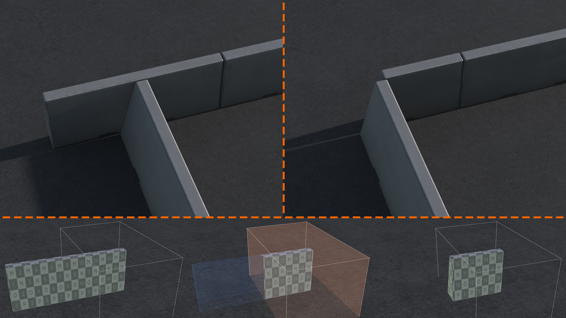
Figure 15 Barrier Trimming Process
3 | The front faces are then passed through a for-loop that uses the material ID on generated primitives to assign a UV offset and material appropriate for its particular advert. We currently pack 4 textures into each texture map, with 20 total variations (4 plain concrete and 16 adverts). Orange end volumes are then booleaned into the concrete and coloured.
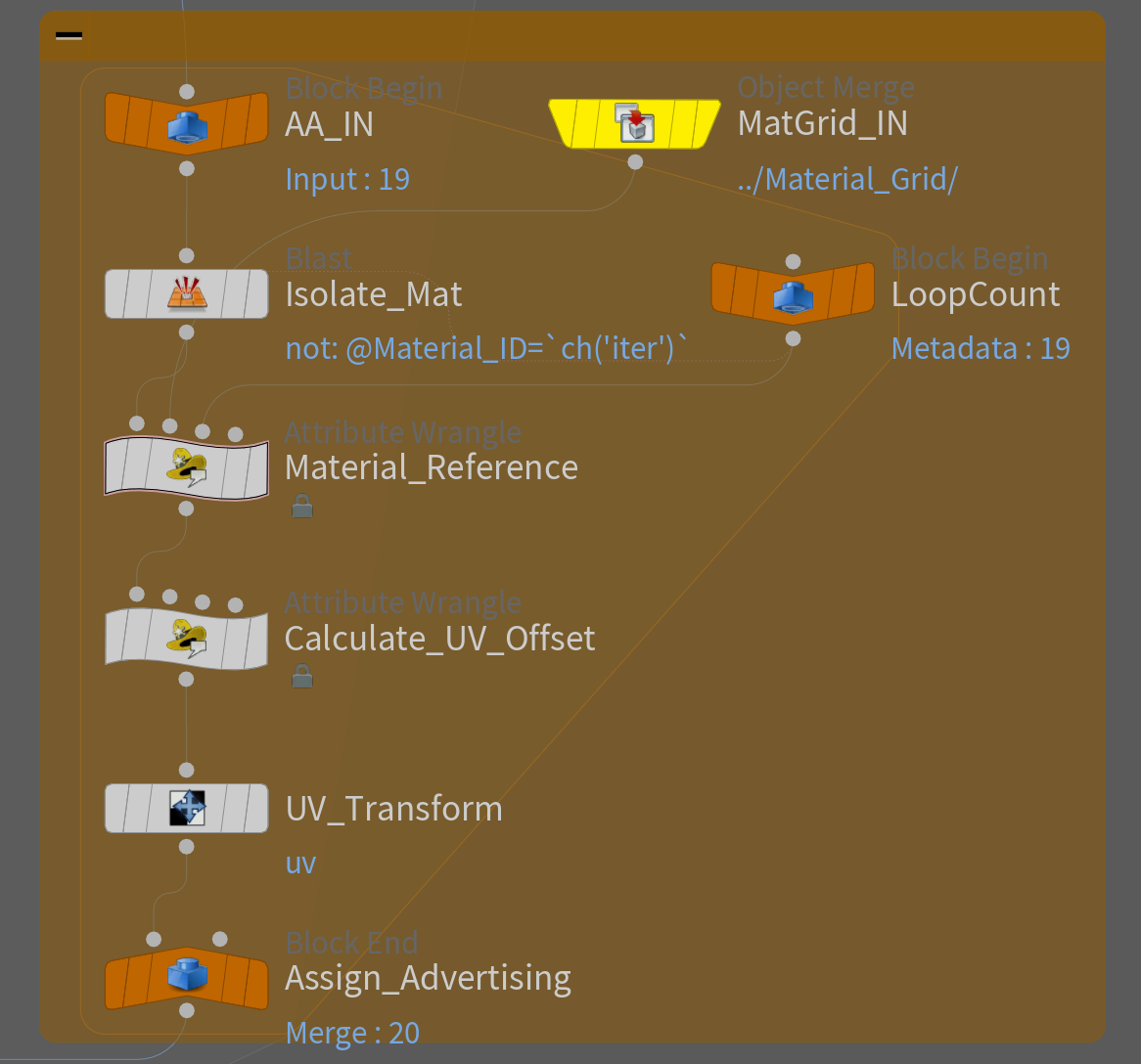
Figure 16 Material Assignment for-loop
4 | In order to create dirt and more variation on the barriers, a secondary UV channel is produced that stacks the barriers into 20 rows to align with a dirt material.
To do this, the UV shells are laid out so that their bottom corner is snapped into the bottom corner of the UV tile. A scale value is then calculated to find the exact amount that UV shell needs to be scaled to fit in 5% of the UV’s height. It is then randomly repositioned into a row, with a random U offset.
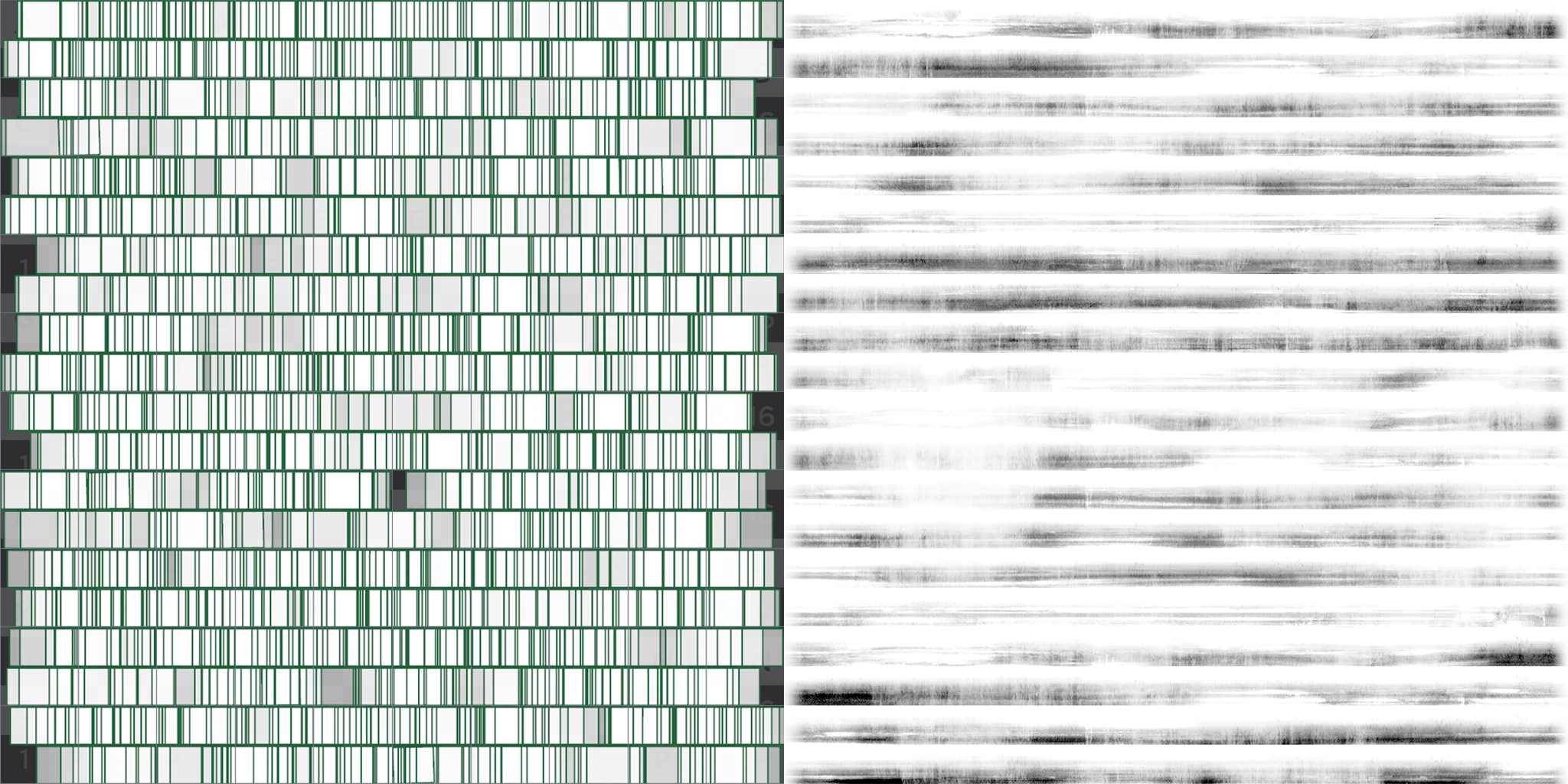
Figure 17 UV2 + Dirt map
Conclusion
There are clicks out there that need saving and we are on a mission to evolve and perfect all of our pipelines to waste as few precious clicks as possible. This generation of our barrier pipeline is a massive improvement over the last in terms of efficiency and stability. It’s true that the barriers are one small piece of the overall puzzle that makes up a racetrack, but every minute we can save by using procedural tools within Houdini is another minute that can be spent improving the accuracy and fidelity of our simulator track models.
George Pennyfather – Technical Artist | Q3D Studios
COMMENTS
Fbaobao 8 months, 3 weeks ago |
非常不错。
SpeLL 8 months, 1 week ago |
Awesome tool!
Please log in to leave a comment.