| On this page | |
| Since | 19.0 |
Overview 
By itself, this nodes doesn’t do anything. You must add spare parameters corresponding to shader or material input attributes. Then when you edit the spare parameters, the node authors equivalent changes to the referenced attributes.
This is a streamlined version of a more generic Edit Properties LOP , but focuses on editing shader and material primitives.
How to 
-
In the Primitives field, set the path(s) to the shader or material primitive(s) you want to edit.
-
Click Create Parameters.
This populates the node with spare parameters taken from the shader or material primitive.
Specialize New Materials 
-
In the Scene Graph Tree, RMB on a Material prim and choose Specialize New Material.
-
This creates an Edit Material Properties node, but configured to specialize new, derivative materials that are based on the ones selected in the Scene Graph Tree.
-
A spare parm Source Material Path is created, to clarify which parameter is the source for our new material. It is channel referenced to Primitives.
=== Override Class of Materials == (override_material_class)
-
In the Scene Graph Tree, RMB on a Material prim. From the submenu New Indirect Editor Nodes, select any of the available Inherit edits options.
-
This creates an Edit Materials Properties node configured with the available Material properties, but setup to apply the edits to the class prim. The overrides are then broadcast throughout the scene, to every material inheriting from that location.
Control pop-up menus 
Tips 
-
In any parameter setting an attribute value, you can use the following local variables:
@numprimThe total number of primitives being modified by this node.
@primIndex of the primitive being modified. This value goes from
0to 'numprim-1.@primpathThe path of the primitive being modified.
-
If a Material has the customData
houdini:dialogScript, this node will use that to create a better editing experience. Currently this can only be authored on Builder subnets inside the Material Library LOP.
This node belongs to a class of nodes that create or edit USD prims directly. These nodes operate in Create mode or Edit mode. This is controlled by a Create primitives checkbox or a Create/Edit popup menu. In create mode, the node creates new prims. In edit mode, the node changes the attributes on an existing prim. The Edit mode has two variations. Edit will not modify primitives which have a houdini:editable attribute set to false. Force edit will modify a primitive regardless of the existence or value of this attribute. This attribute can be set on a primitive using the Configure Primitives LOP.
Parameters that correspond to a USD attribute have a pop-up menu to the left that controls how the node authors the attribute.
In addition to that, any connectable USD attributes (i.e., the ones in the inputs: namespace) will have menu items that allow disconnecting them from their sources.
Pop-up menu item |
Meaning |
|---|---|
Set or Create |
Sets the attribute to the given value, whether it previously existed or not. |
Set If Exists |
Only set the attribute to the given value if it previously existed. Use this mode to make sure an attribute is only set on primitives of the correct type. For example, only |
Block |
Makes the attribute appear to not exist, so it takes on its default value. (If the attribute doesn’t already exist on the prim, this does nothing.) |
Disconnect Input |
Deletes the attribute input connection to its source. Input connections take precedence over attribute values, so disconnecting an input allows the attribute value to take effect. |
Do Nothing |
Ignore this parameter, don’t create or change the attribute in any way. |
Parameters 
Sampling Behavior
Cooking this node can generate many USD time samples, rather than just a single time sample at the current time. This can be equivalent to having a Cache LOP following this node, but it will evaluate much faster, and does not cache data from any other nodes. This allows animated data to be authored to USD without introducing a node time dependency which would then cause all following nodes to also be time dependent. This can vastly improve playback performance of some LOP Networks.
In all sampling modes, if a parameter on this node does not vary with time, and does not rely on other time sampled data from the stage, only a single default value will be generated in USD for the corresponding attribute. USD time samples are only generated for parameters that may vary over time.
Sample Current Frame
A single time sample will be generated for the current time.
Sample Frame Range If Input Is Not Time Dependent
If the input to this node is time dependent, this node behaves as if it is in Sample current frame mode. Otherwise it behaves as if it is in Sample frame range mode.
Sample Frame Range
The Start/End/Inc parameter is used to generate multiple times at which this node’s parameters are evaluated, and a USD time sample is created for each attribute at each one of these times.
Start/End/Inc
When the Sampling behavior is Sample frame range, this parameter controls the number and spacing of base time samples to be generated by this node. The default values of this parameter are @fstart, @fend, and @finc. These values correspond to the start, end, and step size of the global Houdini animation settings when interacting with Houdini. When using a ROP node to generate a range of frames, these values correspond to the start, end, and increment values specified on the ROP node being executed. This default ensures that a USD file written to disk will contain time samples for exactly the frame range requested by the ROP (regardless of the Houdini animation settings).
Subframe Sampling
For each primary sample generated by this node, these parameters can cause additional samples to be generated around that primary sample time. This is most often used to ensure that accurate data exists at exactly the camera shutter open and close times, as well as at the primary sample time.
Shutter
Controls the method used to specify the shutter open and close times relative to the primary sample times.
Specify Manually
The Shutter Open/Close parameter values provide exact offset values relative to the primary sample time.
Use Camera Prim
The Camera Prim parameter provides the scene graph path of a camera primitive from which the shutter open and close times are extracted to provide the offset values relative to the primary time sample.
Shutter Open/Close
When Shutter is set to Specify Manually, these two offset values are added to the primary sample time to indicate the shutter open and close times. The open time should be less than or equal to zero, and the close time should be greater than or equal to zero.
Camera Prim
When Shutter is set to Use Camera Prim, this is the scene graph path of a camera prim on the input node’s stage. The shutter open and close attribute values are read from this primitive.
Samples
The number of subframe samples to create for each primary sample. These samples are evenly distributed between the shutter open and close times. Note that such an even distribution may or may not create a sample at exactly the primary sample time.
Always Include Frame Sample
When turned on, forces a sample to be created at exactly the primary sample time. If the Samples value, together with the shutter open and close times, already place a sample at the primary sample time, turning on this option has no effect. Otherwise, this option causes an addition sample to be added. This means that the actual number of samples per primary sample may in fact be one more than the number specified in the Samples parameter.
Primitives
The primitive(s) the node should operate on. You can drag primitives from the scene graph tree pane into this textbox to add their paths, or click the Reselect button beside the text box to select the primitives in the viewer, or ⌃ Ctrl-click the Reselect button to choose prims from a pop-up tree window. You can also use primitive patterns for advanced matching, including matching all prims in a collection (using
/path/to/prim.collection:‹name›).
Note
This parameter needs to be exposed in order for the transform handles to be context-aware. Without it, the handles may not be positioned properly.
Class Prim Path
Adds an “inherits” composition arc to the edited primitive, to listen at this location for indirect edits. The location does not have to be populated, and it does not cause any primitives to be created.
Create Parameters
Creates spare parameters for editing the values of the input attributes of the material or a shader specified in the Primitives parameter.
Create Material Outputs
Creates spare parameters for editing the connections of the output attributes of the material or a shader specified in the Primitives parameter. They enable changing the terminal shaders of the material.
Initialize Parameters
Changes the state of all control menu parameters to Do Nothing, so that this node will not apply any changes. Also grabs the current values of each property from the first Primitives match, and sets the values of the corresponding parameters to match. This means that changing any parameter’s control menu to Set or Create mode will set the property to its current value, making it easier to apply changes to an existing value rather than setting a brand new value.
Reference Type
This node can edit properties on an existing material primitive or it can create a new on, reference it to an existing primitive, and edit properties on the newly created one. This is useful when the original material is bound to some geometry whose appearance you don’t want to change, but instead you want to base a new material on an existing one, then tweak it, and bind it to another geometry.
None
Don’t create any referencing primitives; edit the properties on an existing one.
Reference
Reference an existing primitive and edit properties on the newly created primitive.
Inherit
Create an “inherits” composition arc to an existing primitive and edit properties on the newly created primitive.
Specialize
Create an “specializes” composition arc to an existing primitive and edit properties on the newly created primitive.
Reference File
Reference an existing primitive in a file on disk and edit properties on the newly created primitive.
Create Class
Edit properties recognized by an existing “inherits” or “specializes” composition arc. The location will be created with an Over specifiers, apart from any Class specifiers set by Class Ancestor. No new composition arcs will be authored.
Class Ancestor
When the Reference type is Create Class, this parameter controls where the Class specifier primitives end and the Over primitives begin. Usually the primitive being modified is a descendant of the primitive where the actual inherit composition arc lives, and all primitives below that point should use the Over specifier, whereas primitives above this point should use Class.
Reference Parent Material
If the Primitives parameter specifies a shader primitive, turning this option on will ensure that the newly created primitive will reference its parent material instead of the shader itself..
Primitive Path
Scene graph path where the new referencing primitive will be created.
Parent Primitive Type
If the prim at Primitive Path doesn’t exist, this node will create it. If it has to create the prim, it will give any intermediate prims it has to create this type.
Make Instanceable
If the toggle is on, the newly created referencing primitive will be instanceable.
Bokeh 
Bokeh Shape
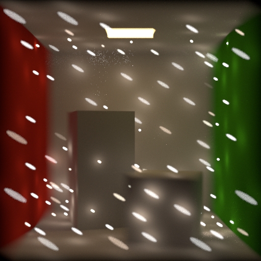
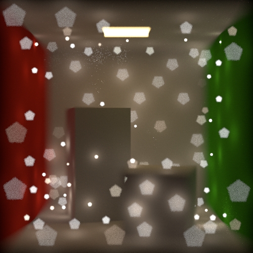
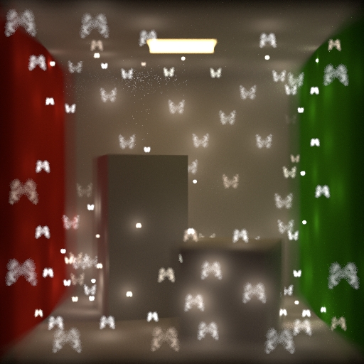
A choice for what shape the bokeh should be: Circular, Polygonal (see Number of sides), or Texture Map (see Bokeh texture map).
Bokeh Texture Map
When Bokeh shape is “Texture map”, this is the path to the texture to use. The texture should contain a bright bokeh shape on a black background.
(The shader samples the texture based on its intensity using importance_remap, shaping the bokeh to the bright parts of the texture).
Number of Sides
When Bokeh shape is “Polygonal”, this is the number of sides the bokeh shape has. This value must be greater than 3.
Bokeh Rotation
Rotate the bokeh shape by this number of degrees.
Anisotropy
This is a value from -1.0 to 1.0 which controls the aspect ratio of the bokeh shape. Set this to 0 to get square (equal height and width) shapes. Negative fractions make the bokeh shape narrower than it is tall. Positive fractions make the bokeh shape shorter than it is wide.
Anisotropy Texture Map
A texture map to control anisotropy (see the Anisotropy parameter above) for each pixel. In the texture image, black represents -1.0 and white represents 1.0.
Lens Distortion 
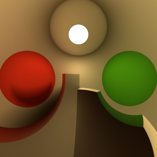
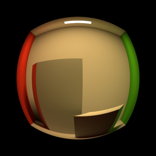
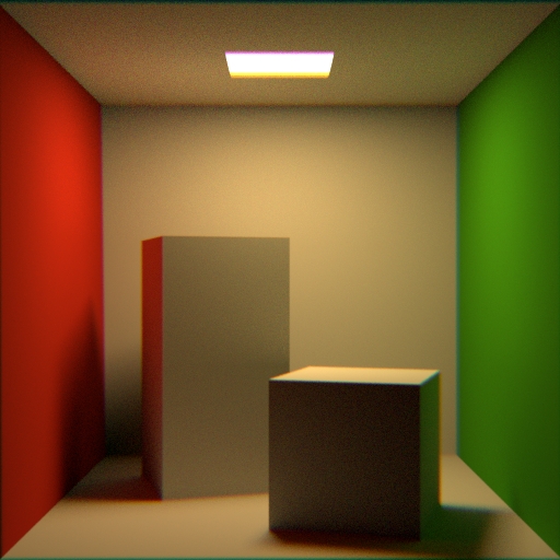
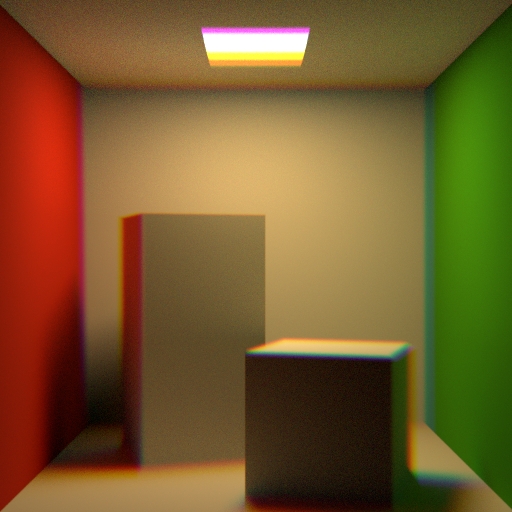
Projection
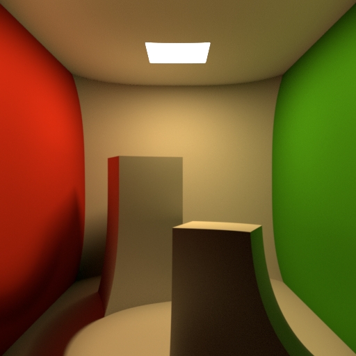
Change the projection type of the lense.
Perspective creates a default view of the world in front of the camera. This type can capture the depth of different objects. Orthographic creates a view of the world in front of the camera. This type can`t capture the depth of the different objects. Polar creates a 3-dimensional panoramic view around the camera. You can use the result in a dome-shaped world, for example a sky. Cylindrical creates a 3-dimensional panoramic view similar to the Polar view. Here the shape, that is used to enclose the camera, is a cylinder instead of a sphere. Polar Stereographic projection is used if preserving the shape of small object on image plane is required. Polar Equidistant projection is used if preserving angular sizes of object on image plane is required. Polar Equisolid projection is used if preserving constant ration of solid angles in object and image spaces is required. Polar Orthographic projection is used if evenness of illumination through the entire image plane is required.
Type of Curvature
A type of curvature to distort the lens with: “None”, “Quadratic”, “Cubic”, or “Texture Map”.
Curvature Texture Map
When Curvature type is “Texture map”, this is a path to the texture map. Values in the texture image represent the unit “height” of the lens (distance from flat) at a given position across the face of the lens. Black represents -1.0 and white represents 1.0.
Lens Curvature
When Curvature type is not “None”, this is the amount of curvature to apply, from -1.0 to 1.0.
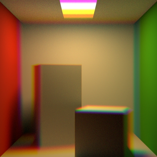
Chromatic Aberration
The amount of chromatic aberration to add to the lens.
This value plus one represents the index of refraction applied to blue light. The shader then linearly maps this value down to an index of refraction of 1.0 for red light. For example, a value of 0.2 means the index of refraction is 1.2 for blue light and 1.0 for red light, with a linear gradient in between.
For more control over the mapping use the Aberration ramp.

Aberration Ramp
This ramp controls the mapping of aberrations between blue and red light. The left edge of the ramp represents blue light and the right edge represents red light. The vertical axis represents the index of refraction and goes from 1.0 at the bottom to 1.0 + the value of Chromatic Aberration at the top.
Tint and Exposure 
Tint
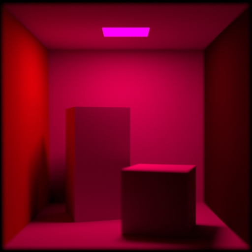
Adds a color tint to the output. You can use numbers greater than 1.0 to (unrealistically) brighten the image.
Tint Texture Map
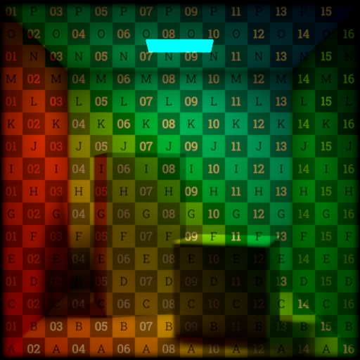
Effectively multiplies this texture map over the output image.
Exposure
An exponential scale for the brightness of the image.
Intensity
A linear scale for the brightness of the image.
Vignetting
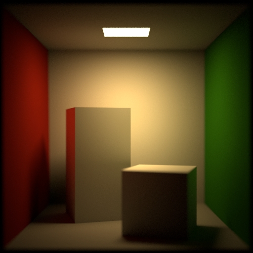
An amount to darken the image around the edges. Because this is physically based, it is relative to the camera’s field of view. Alternatively, you can use the Tint texture map to get full control over darkening parts of the image.
Tilt and Shift 

Tilt X
The number of degrees to tilt the plane of focus by in the X direction (around the camera’s Y axis).
Tilt Y
The number of degrees to tilt the plane of focus by in the Y direction (around the camera’s X axis).
Shift X
The distance (in Houdini world units) to shift the lens in the X direction.
Shift Y
The distance (in Houdini world units) to shift the lens in the Y direction.
Focus Mapping 
F-Stop Texture Map
The path to a texture map that specifies the f-stop value at each pixel. In the texture image, black represents F-stop near and white represents F-stop far.
F-Stop Near
The lower bound of the F-stop texture map.
F-Stop Far
The upper bound of the F-stop texture map.
Focus Texture Map
The path to a texture map that specifies the focus distance at each pixel. In the texture image, black represents Focus near and white represents Focus far.
Focus Near
The lower bound of the Focus Texture Map.
Focus Far
The upper bound of the Focus Texture Map.
OpenCV 
Radial distortion and tangential distortion are the two major forms of distortion. Radial distortion is calculated as shown below:
Tangential distortion follows this rule:
To describe the amount of distortion you need to find at least five distortion parameters k and p:
There are also the intrinsic and extrinsic parameters of the camera. Intrinsic parameters are specific to a camera. They include information like focal length f and optical centers c. Both are used to create a camera matrix to remove distortion due to the lenses of a specific camera. The camera matrix is unique to a specific camera, so once calculated, it can be reused on other images taken by the same camera. It is expressed as a 3×3 matrix:
Extrinsic parameters correspond to rotation and translation vectors.
Enable OpenCV Distortion
Turn this on to use an the OpenCV defined intrinsic camera parameters for lens distortion.
Refer to OpenCV documentation for more details on each of the constants in the intrinsic camera parameters.
k1
The k1 radial distortion constant in the intrinsic camera parameters defined by OpenCV.
Positive values will produce a barrel distortion, and negative values will produce a pincushion distortion.
k2
The k2 radial distortion constant in the intrinsic camera parameters defined by OpenCV.
Positive values will produce a barrel distortion, and negative values will produce a pincushion distortion.
k3
The k3 radial distortion constant in the intrinsic camera parameters defined by OpenCV.
Positive values will produce a barrel distortion, and negative values will produce a pincushion distortion.
k4
The k4 radial distortion constant in the intrinsic camera parameters defined by OpenCV.
Negative values will produce a barrel distortion, and positive values will produce a pincushion distortion.
k5
The k5 radial distortion constant in the intrinsic camera parameters defined by OpenCV.
Negative values will produce a barrel distortion, and positive values will produce a pincushion distortion.
k6
The k6 radial distortion constant in the intrinsic camera parameters defined by OpenCV.
Negative values will produce a barrel distortion, and positive values will produce a pincushion distortion.
p1
The p1 tangential distortion constant in the intrinsic camera parameters defined by OpenCV.
Positive values will give the effect that the top of the image plane is farther away than the bottom, and negative values will do the opposite.
p2
The p2 tangential distortion constant in the intrinsic camera parameters defined by OpenCV.
Positive values will give the effect that the right side of the image plane is farther away than the left side, and negative values will do the opposite.
Shutter 
Rolling Shutter Direction
A choice for how to simulate rolling shutter: “None”, “Bottom First”, “Top First”, “Left First”, “Right First”, or “Custom” (see Time offset curve below).
Time Offset Ramp Rotation
When Rolling shutter is “Custom”, the direction of the shutter movement, in degrees. A value of 0 represents straight up (positive Y in camera space).
Time Offset Ramp
When Rolling shutter is “Custom”, this ramp to control the progression of the shutter across the image. See understanding time offset and scale above. The horizontal axis represents shutter time, the vertical axis represents shutter progress, where the bottom is the start position and the top is the end position. So, the default ramp (a line from bottom left to top right) represents a linear progression across the image.
Time Offset Texture Map
Path to a texture map file to control the time offset. See understanding time offset and scale above.
Time Scale
A base scale on the shutter time. Basically, this affects how blurry the image is, however see understanding time offset and scale above for more information. For rolling shutter effects time scale must be quite small, otherwise the rolling shutter will not be visible.
Time Scale Texture Map
Path to a texture map file to control the time offset. See understanding time offset and scale above.
Use Shutter Curve
Turn this on to get custom control over the amount of light allowed into the camera aperture across the shutter time.
Shutter Curve
When Use shutter ramp is on, the ramp represents the weighting of a time sample based on it’s position in the shutter period. In terms of a camera, this ramp represents how much light gets through to the sensor (vertical axis) at a given moment across the the shutter time (horizontal axis). The default distribution is uniform.


