| To... | Do this |
|---|---|
|
Control the quality (level of detail) of the simulation |
Increase the Particle Separation parameter on the |
|
Get precise and fast animated colliders |
Always use the Animated (Rigid) Collider Type when possible. This provides very precise interpolations between frames. If you look at the MPM Configure Spinning Tire example, the material is being moved using just friction, without needing to add any custom velocity fields. |
|
Prevent MPM particles from going through thin colliders |
|
|
Get smooth continuous emission without stepping artifacts |
On the
|
|
Apply forces to the simulation |
Although MPM is in SOPs, you can dive inside the |
|
Simulate thin objects like a sheet of metal or a hollow object |
In the Points from Geometry section there is a Type parameter that’s set to Volume by default, which fills the geometry with particles. Changing this to Surface will instead cover the geometry surface with particles. However, the scatter may cause holes to appear in the geometry, which could make it difficult to render or retarget. Turn on Relax Iterations to more evenly distribute the particles.
|
|
Pin particles in space to prevent them from moving |
Use the parameters in the Pin Constraints section of the The MPM Configure Softbody example is a great demonstration of how to pin a Point Group. The inner points are isolated, and an |
|
Prune out points shooting outside of the visible simulated domain |
This is useful if you have something exploding or has a lot of splash.
|
|
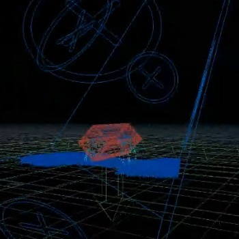
Reduce the effect of materials sticking to each other |
Reduce the Grid Scale in the Resolution section of the The background grid is shared when there are two materials simulated together. When you have two points very close to each other, the material will behave half like material A and half like material B within the voxel because they're sharing the material property. Reducing the Grid Scale will reduce the bleeding between materials. In the following example, water is dropped onto a mound of soil, but it does not run off as expected. Changing the Grid Scale to 1 means the voxel will be roughly the same size as the particle. Once we do this, the water is able to run off and even carry some of the soil particles with it, creating a more realistic look.
|
|
Run a simulation in slow motion |
For an example of how to set this up, see the MPM Configure Spinning Tire example. |
|
Make the simulation run faster |
Reduce the Substeps Max parameter in the Iterations section of the You can do this if you feel like the system is too conservative and you could get similar results with lower substeps. However, lowering this value too much can cause the simulation to become unstable. You could also try increasing the CFL Condition and Material Condition, which would relax the velocity and stiffness constraints and could speed up the simulation. |
|
Fix wiggling in materials that should not wiggle (such as wet sand) |
Increase the Stiffness (E) in the Material section of the For example, you can multiply each existing value by |
|
Fix bouncing in materials that should not bounce (such as snow) |
Increase the Critical Compression, Critical Stretch, and Stiffness (E) in the Material section of the This will make the material compress a little more, but will get rid of the bouncing when it settles. |
|
Fix fast moving particles from collapsing mid-air or creating a staircase pattern around the edges |
Increase the Max Voxel Dilation in the Simulation section of the Since the simulation is sparse, sometimes the background grid doesn’t extend fast enough to keep up and cover the area where the particles are going, when they are moving very quickly. This can cause the shape of the material to collapse and show the pattern of the voxels. Increasing this value will expand the active region. The reason the max value is low by default is to account for cases where you have crazy explosions with particles that are flying out of the simulation. The active regions are clamped to avoid running out of GPU memory and the simulation crashing.
|
|
Fix a simulation where materials have changing properties and become unstable |
Turn off the Assume Unchanging Material Properties checkbox on the Advanced tab of the By default the MPM Solver assumes that material properties are constant throughout the simulation. This is an optimization that prevents the solver from recomputing the Material Condition on every frame. However, if you have material properties that change as the simulation runs, it could become unstable if the substeps aren’t adjusted appropriately. Turning this off will slow down the simulation, but will ensure stability by keeping the Material Condition consistent. |
|
Get some MPM particles to follow an animated target |
In the Pin Constraints section of the
|
|
Create a collider with variable friction |
|
|
Easily point deform non-fracturing objects (such as rubber or jello) |
|
|
Add variation to the way the material behaves and fractures |
You can do this using an float noise = fit(abs(snoise(@P*5,5,0.5,1)), 0, 0.25, 0, 1); @E *= fit01(noise, 1, 4); For example, this code generates a noise value, then scales it and stores it as |
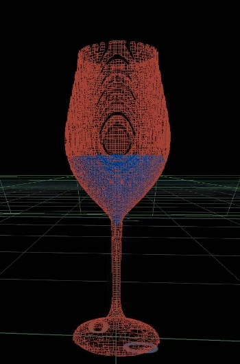 Original mesh
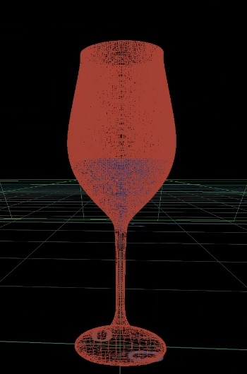 Finer mesh after increasing the Voxel Size
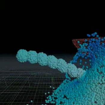 Before increasing the Global Substeps
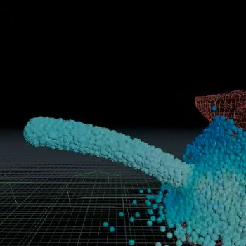 After increasing the Global Substeps
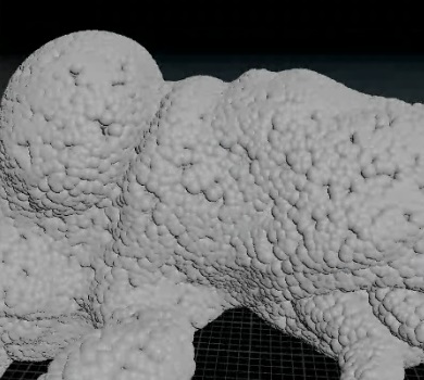 Before turning on Relax Iterations
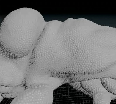 After turning on Relax Iterations
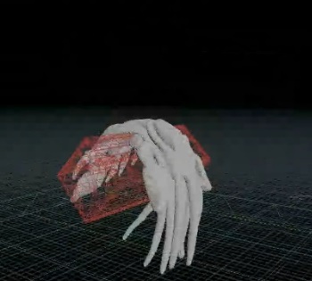 Hollow Squab dropped on a box
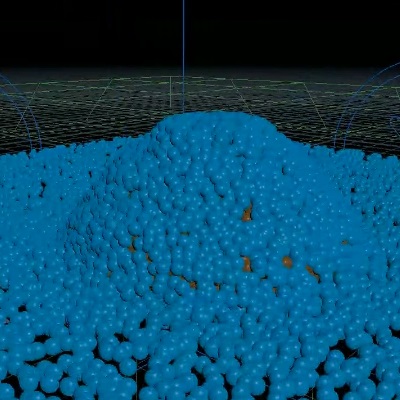 Before changing the Grid Scale
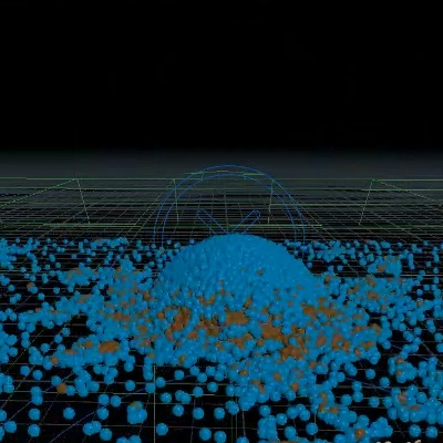 After changing the Grid Scale
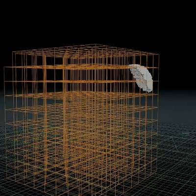 Before increasing the Max Voxel Dialation
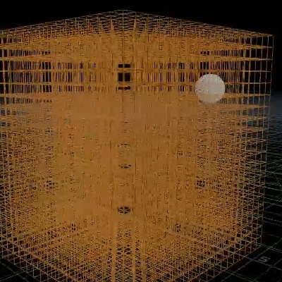 After increasing the Max Voxel Dialation
 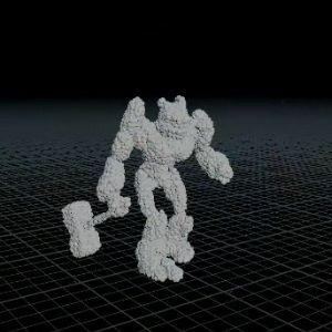 Before pinning points to animation
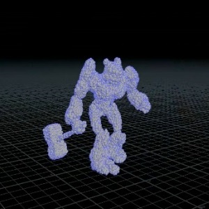 After pinning points to animation
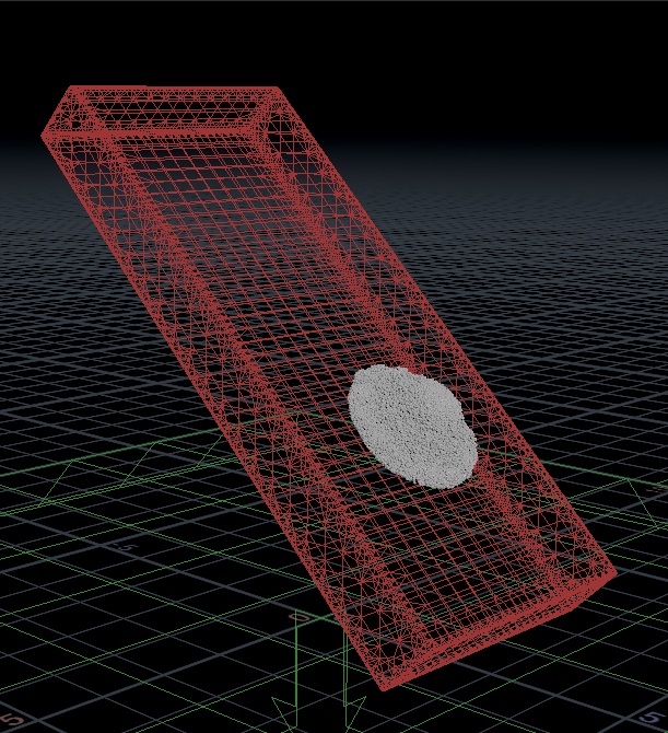 No friction
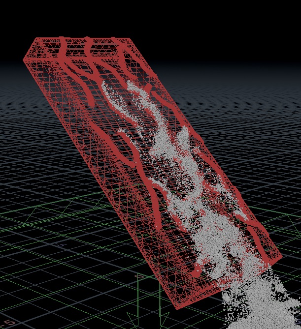 Painted areas have friction