| On this page |
You can create simulated motion and collision effects for your KineFX characters by running them through a Bullet solver RBD (rigid body dynamics) simulation with the
Ragdoll Collision Shapes SOP,
Ragdoll Constraints SOP, and
Ragdoll Solver SOP nodes and their associated workflows.
Core workflow 
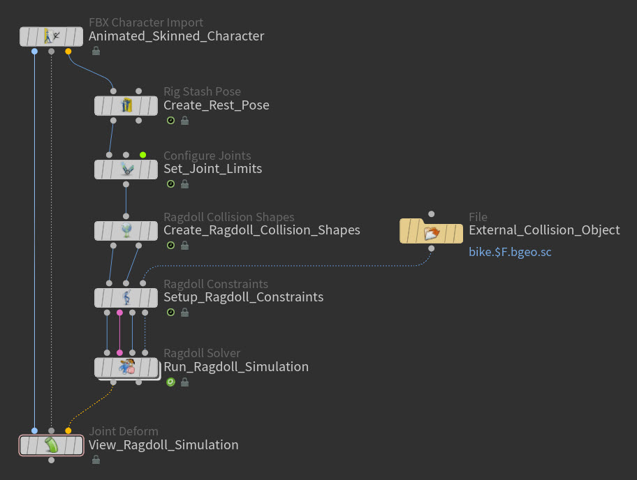
1. Import your rigged character 
Bring the rigged character into KineFX that you want to set-up the ragdoll simulation for, or create a rigged character in KineFX.
For more information about these processes, see Bringing animation and character data into KineFX, Working with skeletons, and Transferring animation.
2. (Optional) Define a rest pose for your ragdoll character 
Make sure that your character has a t-pose or rest pose (rest_transform). Your character needs to be in its rest position for each step of the ragdoll simulation set-up process.
Do one of the following:
-
If your character already has a rest pose, then move on to step 3.
-
If your character does not have a rest pose, then create a
Rig Stash Pose SOP node, connect it to your character, and then use it to create a new rest pose for the character.
3. Set joint limits for the major joints in your ragdoll character’s skeleton 
If you want your character’s limbs and body to bend in natural ways when it ragdolls, then you need to restrict the rotations of its joints. You can define the joint limits for your character’s skeleton with the
Configure Joints SOP node.
You do not need to define the joint limits for all the joints in your character’s skeleton. In many cases it is sufficient to define the joint limits for only the major joints (the main articulation points) in your character’s skeleton like the hips, knees, ankles, shoulders, elbows, wrists, and spine.
Important
When using a Configure Joints SOP node in your ragdoll set-up, it needs to use the rest pose. Please make sure that you place a Rig Stash Pose SOP node upstream of the Configure Joints SOP to create rest_transform, and that you also turn on the Rest Pose Attribute parameter on the Configure Joints SOP node itself.
4. Create the collision shapes for your ragdoll character 
For your ragdoll character to be able to collide with any collision objects in their environment (like the ground plane or an environment piece they may walk into), they need a set of collision shapes. Collision shapes define the collision bounds for a character.
You can automatically generate a set of simple primitive collision shapes for your character with the
Ragdoll Collision Shapes SOP node.
-
Create a Ragdoll Collision Shapes SOP node and connected it to the upstream nodes in your ragdoll character’s network.
-
In the Parameter Editor, turn on the Rest Pose Attribute parameter and then set it to the rest position attribute that is on your character. By default, this is
rest_transform. -
Set any of the other general Ragdoll Collision Shapes SOP
parameters you desire.
-
Create a Collision Shape multiparm for every collision shape you want to create.
For each Collision Shape multiparm, do the following:
-
Click the arrow icon next to the Group field, select the joint you want to create the collision shape for in the viewport, and then press Enter. The
@nameof the ragdoll skeleton joint you selected for the collision shape appears in the Collision Shape multiparms’s Group field, and the new collision shape appears on the target joint in the viewport. -
Use the Shape parameter to select a primitive shape for the collision shape. You can choose from Capsule, Box, or Sphere.
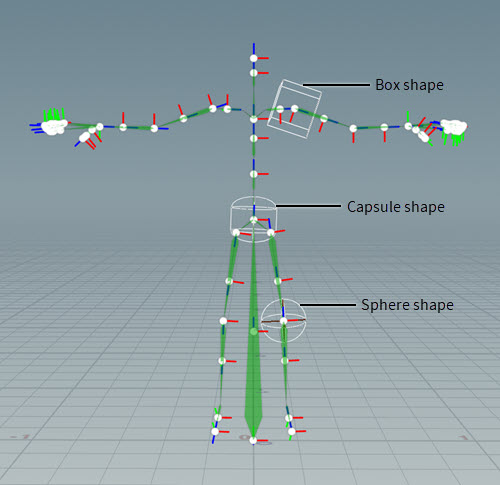
Collision shape primitives -
Use the transform parameters (Translate, Rotation, and Scale) to position and resize the shape. You want the shape to be as close as possible to the character’s skin.
-
-
Once you have finished creating all the Collision Shape multiparms and their collision shapes, type the names of all the joints you created collision shapes for in the Group parameter’s field using the
@namesyntax. For example,@name=pelvis. This tells the ragdoll solver which collision shapes to use when it computes the simulation.
Tip
If you want to learn how use custom collision shapes in your ragdoll simulation set-ups, see Example 3: Custom collision shape geometry.
5. Create the constraints for your ragdoll character 
There are two types of constraints that your ragdoll character can have: internal constraints and external constraints. Internal constraints hold your character’s skeleton together and keeps its collision shapes on its skeleton during the ragdoll simulation. The external constraints allow you to constrain the joints in your character’s skeleton to other joints or external collision objects.
You can automatically generate constraints for all the joints in your ragdoll character that have collision shapes with the Ragdoll Constraints SOP node.
-
Create a Ragdoll Constraints SOP node and connect its first input to the first output on the
Ragdoll Collision Shapes SOP node, and then connect the Ragdoll Constraints SOP node’s second input to the second output on the Ragdoll Collision Shapes SOP node.
-
Connect the external collision objects you want to use with your ragdoll constraints to the third input on the Ragdoll Constraints SOP node.
-
In the Parameter Editor, keep the default setting for the Rest Pose Attribute parameter. You character needs to be in its rest position when its constraints are created.
-
Since you set joint limits for your ragdoll character’s joints, you need to turn on the Configure Attribute parameter so that the internal constraints use the joint angle restrictions you set up with the
Configure Joints SOP node.
-
Use one of the Missing Rotation Limits parameter settings if you want to automatically create internal constraints for all the joints in your ragdoll character’s skeleton that do not have joint limits defined for them.
-
Set all the Internal Constraint parameters you need to get the constraint behavior you desire.
-
In the External Constraints section, create a Constraints multiparm for every joint in your ragdoll character’s skeleton that you want to pin to another joint or an external collision object (as supplied by the third input on the Ragdoll Constraints SOP node).
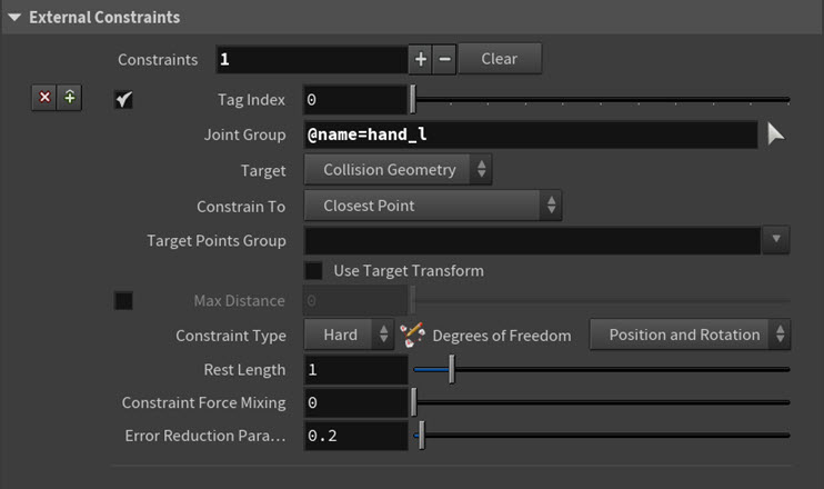
Constraints multiparm settings For each Constraints multiparm, do the following:
-
Click the arrow icon next to the Joint Group parameter, select the joint you want to constrain in the viewport, and then press Enter. The name of the joint you selected appears in the Joint Group field.
-
Select a Target for the constraint. You can choose from an external collision object (Collision Geometry) or another joint (Skeleton).
-
If you selected Target ▸ Collision Geometry, then you also need to use the Constrain To parameter options to choose how the constraint will look for its Target.
-
If you want to restrict where the constraint looks for its target to a specific primitives group or set of joints, then use the Target Points Group or Target Primitives Group's drop-down list to select the primitive groups or sets of joints you want to restrict the search to.
-
If you want to orient the constraint to its target’s transforms, turn on Use Target Transform.
-
Use the Constraint Type parameter to choose your constraint’s type. Your constraint can be either Hard, Soft, or Glue.
A Hard constraint strictly constrains the position and/or rotation of a ragdoll skeleton joint with no allowable movement. A Soft constraint strongly constrains the position and/or rotation of a ragdoll skeleton joint, but allows a small amount of movement (as determined by the Stiffness parameter). And a Glue constraint strongly constrains a ragdoll skeleton joint to an external collision object or other joint until the force (generated by the physics solver) applied to it is greater than the specified Strength parameter value, and then the bond breaks.
-
Set all the Constraint Type-related parameters as you desire.
-
Tip
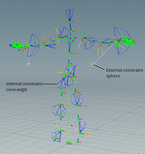
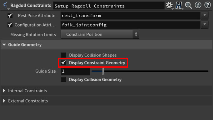
You can view the internal and external constraints for your ragdoll character in the viewport when you turn on Display Constraint Geometry in the Guide Geometry section of the Ragdoll Constraints SOP’s parameters.

6. Run the ragdoll simulation for your character 
Now that you have created and customized all the necessary components of the simulation—the joint limits, the collision shapes, and the constraints—for your ragdoll character, you can create and configure the Bullet physics solver that will compute the simulation.
You can create this solver with the
Ragdoll Solver SOP node.
-
Create a Ragdoll Solver SOP node and connect its first, second, and third inputs to the first, second, and third outputs on the
Ragdoll Constraints SOP node.
-
If you supplied external collision objects on the Ragdoll Constraints SOP node’s third input, then connect the Ragdoll Solver SOP node’s fourth input to the Ragdoll Constraints SOP node’s fourth output. If you did not and you still want to use external objects as Collision Geometry in your simulation, then connect your external collision objects to the Ragdoll Solver SOP node’s fourth input.
-
In the Parameter Editor, set all the
parameter settings you need to achieve the behavior you are looking for in your ragdoll simulation.
-
The general Solver parameters specify settings for the solver like the scale value for the time step (Time Scale) used by the solver, the resolution of the simulation (Number of Substeps), the accuracy of the ragdoll constraints (Constraint Iterations), and whether or not gravity is used for the simulation (Gravity).

General Solver parameters -
The Ground Plane parameters allow you to create a collision ground plane (Add Ground Plane ▸ Ground Plane) for your ragdoll simulation and configure its transforms (Position and Rotation), elasticity (Bounce), and slipperiness (Friction).

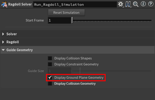
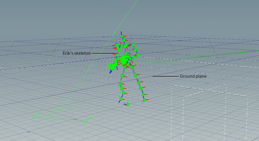
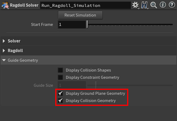
Ground Plane parameters You can view the ground plane in the viewport when you turn on Display Ground Plane Geometry in the Guide Geometry section of the Ragdoll Solver SOP’s parameters.


Display Ground Plane Geometry = on -
The Collision Geometry parameters specify the settings for the external collision objects connected to either the third input on the Ragdoll Constraints SOP node or the fourth input on the
Ragdoll Solver SOP node.
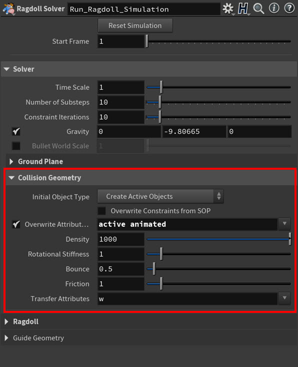
These settings determine the initial state for the collision objects (Initial Object Type), how the collision objects are imported or updated each time step (Overwrite* parameters), the mass of the objects (Density), the inertial tensor multiplier for the objects (Rational Stiffness), the elasticity of the objects (Bounce), and the slipperiness of the objects (Friction).

Collision Geometry parameters You can view your external collision geometry in the viewport when you turn on Display Collision Geometry in the Guide Geometry section of the Ragdoll Solver SOP’s parameters.

Guide Geometry parameters 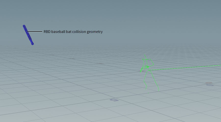
Display Collision Geometry = on
-
-
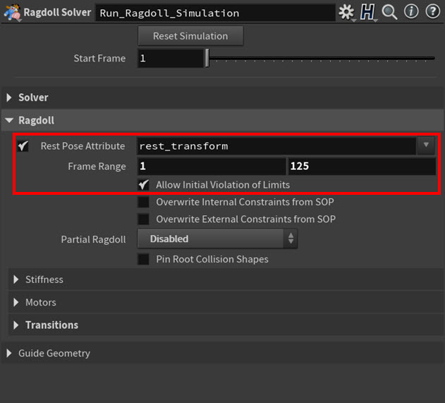
The general Ragdoll parameters specify settings like what rest pose is used for the simulation (Rest Pose Attribute), the duration of the simulation (Frame Range), how constraints are imported per time step (Overwrite* parameters), whether or not rotation limit violations are ignored on initialization (Allow Initial Violation of Limits), and whether or not any partial ragdolling is used in the simulation (Partial Ragdoll).

General Ragdoll parameters -
The Stiffness parameter settings add resistance to the solver’s attempts to move points from their current orientations to their target (animated or simulated) orientations.

Stiffness parameters -
The Motors parameter settings determine how much effort the solver will put into trying to make points follow their animation clip. This is useful when you are trying to make a ragdoll character’s joints stay closer to their rest positions.

Motors parameters -
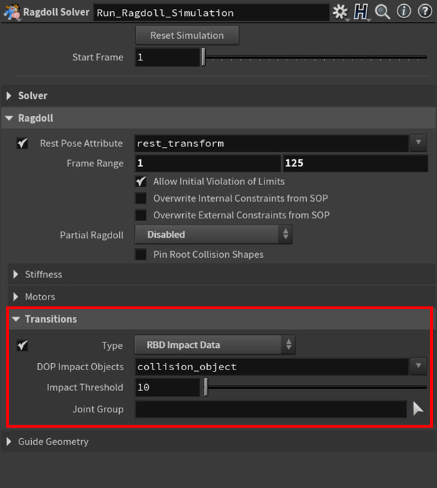
The Transitions parameter settings define the criteria that triggers a character to transition to its ragdoll simulation.

Transitions parameters -
The Locomotion parameters are only available when using a Transitions ▸ Type that is triggered by a character moving or rotating through world space. These transition types require your character’s locomotion (and their locomotion joint) in order to accurately calculate when its skeleton meets the trigger conditions. This section provides internal locomotion settings that compute locomotion inside the Ragdoll Solver SOP node, but you can also use an external
Extract Locomotion SOP node to compute these settings upstream.

Locomotion parameters
-
-
-
7. View the results of your ragdoll simulation 
Use a Joint Deform SOP node to view the results of your ragdoll simulation in the viewport.
Ragdoll examples 
Example 1: Ragdoll set-up with external constraints and motors 
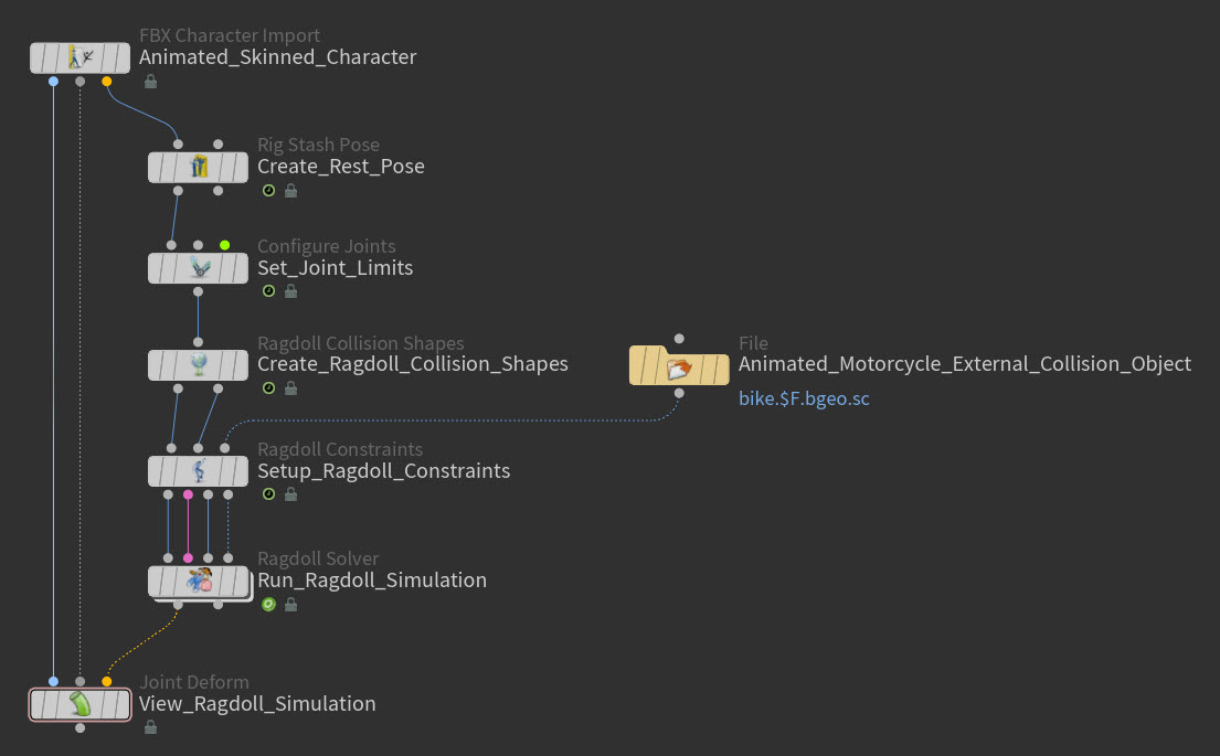
In this example ragdoll set-up, Erik is constrained to an animated motorcycle external collision object and he tries to follow the motorcycle’s animation while maintaining a good posture.
For this character, the first thing that is created for Erik is his rest position. This is because Erik needs to be in his rest pose when we set his joint limits, create his ragdoll collision shapes, set up his ragdoll constraints, and run his ragdoll simulation.
The
Rig Stash Pose SOP node creates the
rest_transform attribute and stores (Mode ▸ Store) Erik’s current pose (Erik seated on the motorcycle) as his rest pose (Attribute Name) for the simulation.
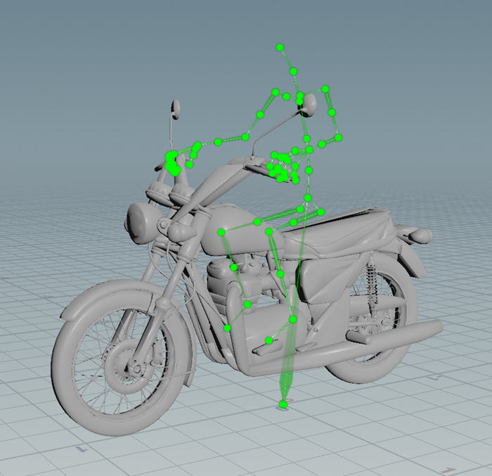
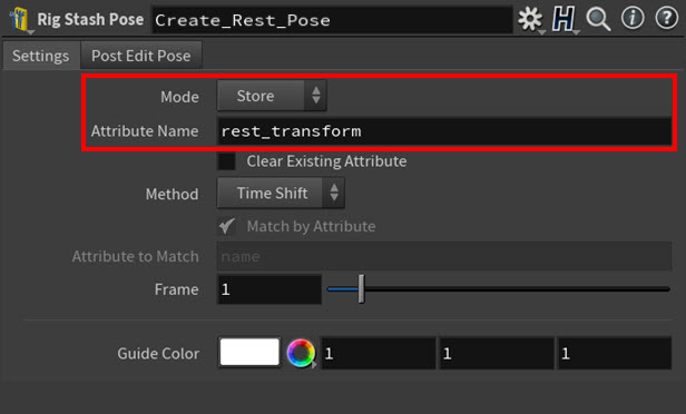
The
Configure Joints SOP node puts Erik’s skeleton in its rest position (Rest Pose Attribute), defines the rotation limits (Configurations multiparms) for the all the major joints in Eric’s skeleton (like the knees, elbows, hips, shoulders, and so on), and then saves those limits to the
fbik_jointconfig attribute (Output Configuration). These limits restrict how far those joints can move from their rest positions during the ragdoll simulation, and they prevent Erik’s limbs or spine from bending at odd angles. Mode is set to Ragdoll because only joint limits for rotation are required for this set-up.
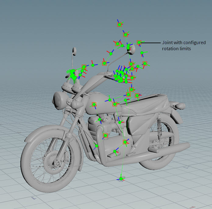
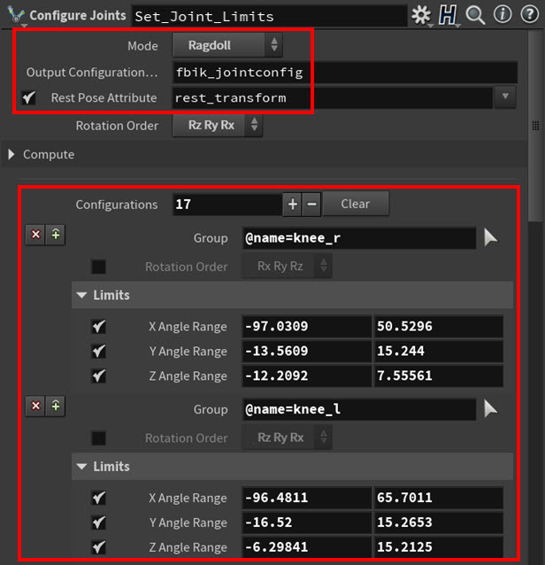
The
Ragdoll Collision Shapes SOP node puts Erik’s skeleton in its rest position (Rest Pose Attribute) and then creates the collision shapes for the ragdoll simulation based on the Collision Shapes multiparm settings. These shapes allow Erik to collide with external collision objects like the motorcycle, but they do not allow the motorcycle to collide with Erik.
Tip
If you want to learn how to swap in custom collision shapes for your own ragdoll simulation set-up, see Example 3: Custom collision shape geometry.
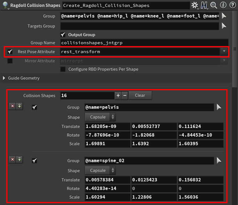
Each collision shape is a simple capsule primitive that is linked to a specific joint (or joints) in Erik’s skeleton. They also follow the general volume of Erik’s model to best represent his topology.
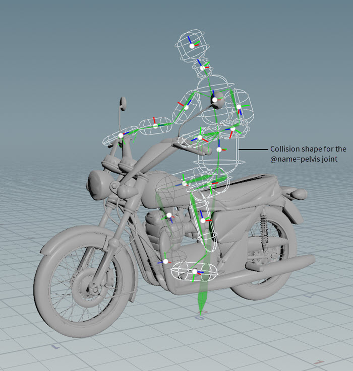
All the joints listed in Group are also output (Output Group) to a point group (Group Name) on the collision shapes.
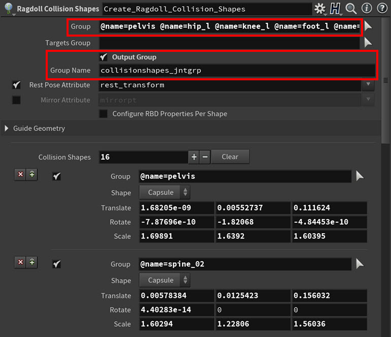
The Ragdoll Constraints SOP node puts Erik’s skeleton in its rest position (Rest Pose Attribute) and then creates an internal constraint for every joint in Erik’s skeleton that has a collision shape using the rotation limits (Configuration Attribute) set up by the Configure Joints SOP. These ragdoll constraints keep Erik’s body together and his limbs in the right positions during the ragdoll simulation.
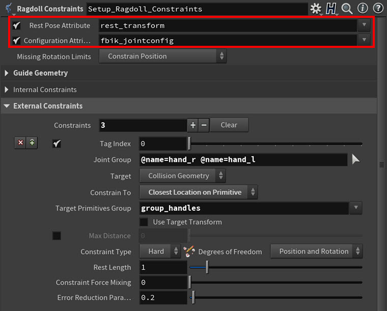
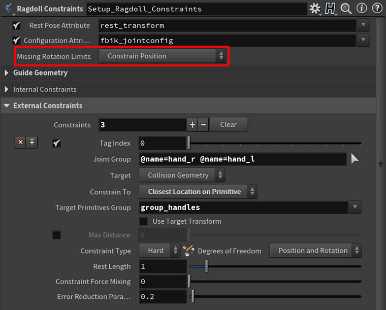
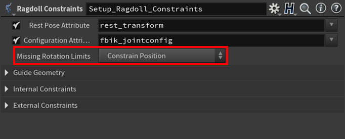
Also a cone twist constraint is automatically created (Missing Rotation Limits ▸ Constrain Position) for any joint in Erik’s skeleton that does not have a collision shape.
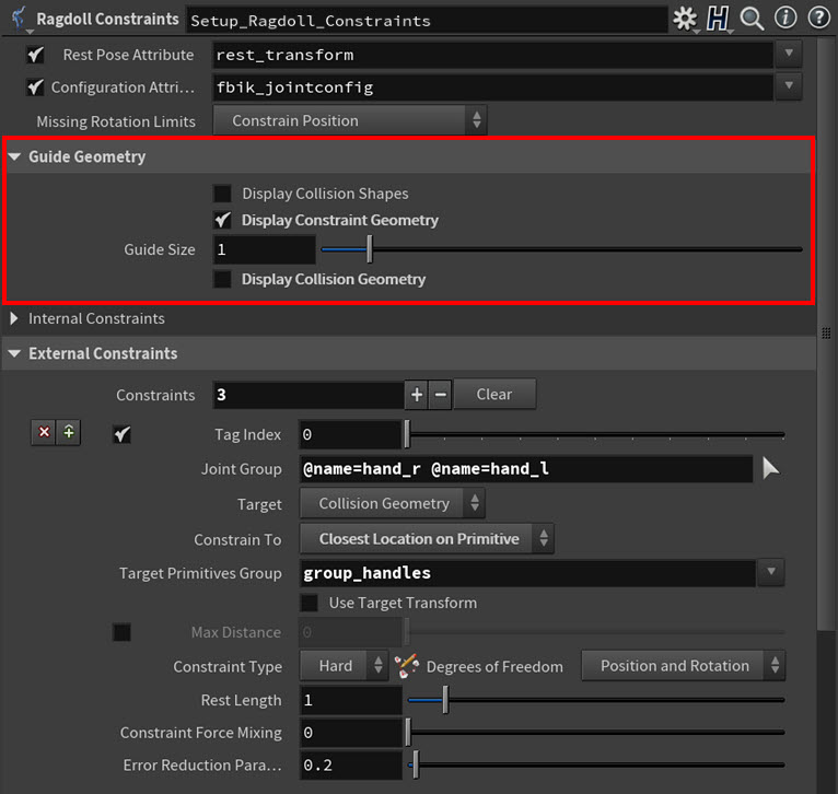
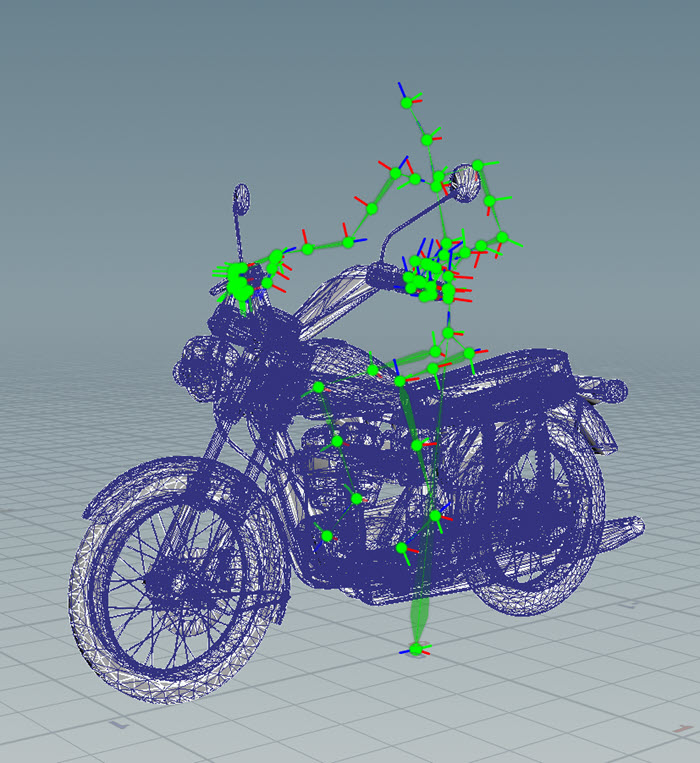
When Guide Geometry ▸ Display Constraint Geometry = on, you can see both the internal constraint cone angles (which reflect the joint limits that were set up with the
Configure Joints SOP node) and the white spheres that represent each external constraint.
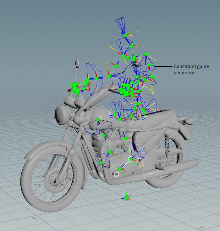
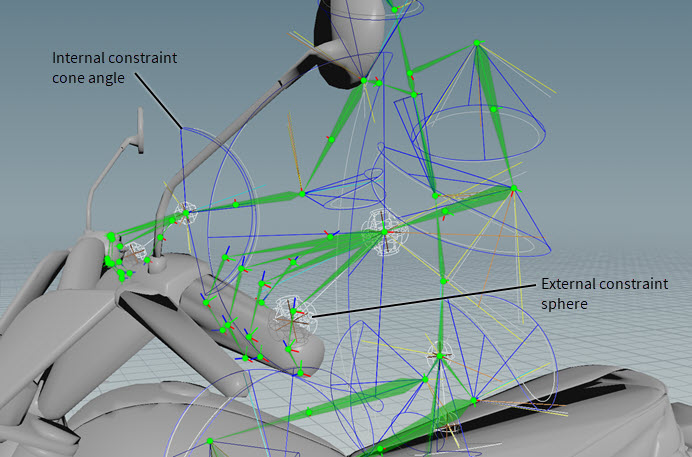
Erik’s Internal Constraints are set to the default values (the default settings tend to give good results out-of-the-box), but his External Constraints are customized. We were able to set-up external constraints for Erik because we supplied an external collision object—the motorcycle—on the Ragdoll Constraints SOP node’s third input.
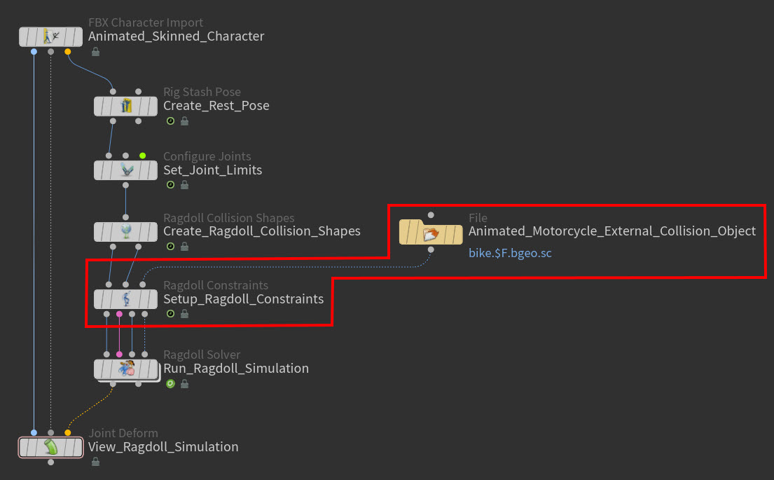
When Guide Geometry ▸ Display Collision Geometry = on, the external collision geometry in the scene (like the motorcycle) appears as a blue meshes.
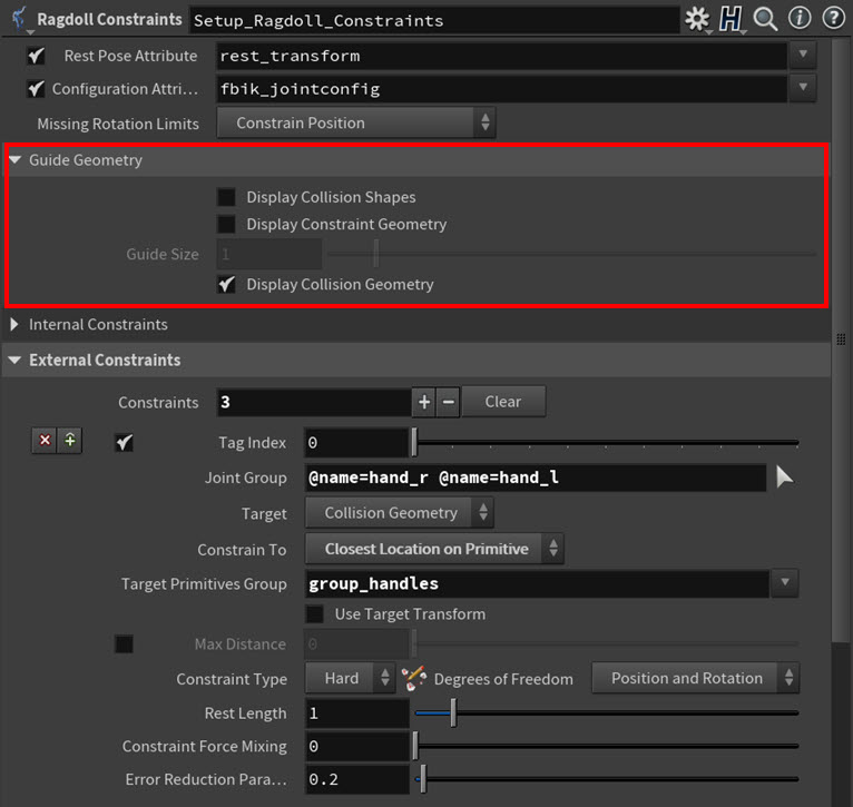
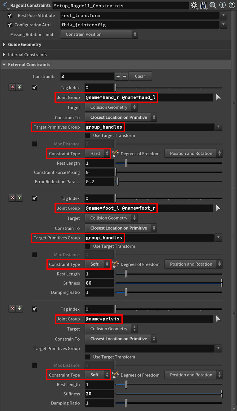
Each External Constraints ▸ Constraints multiparm creates either a hard, soft, or glue (Constraint Type) constraint for the joints specified in Joint Group. For Erik, only hard and soft constraints are used. These constraints are the only things holding Erik on the motorcycle during its animation.
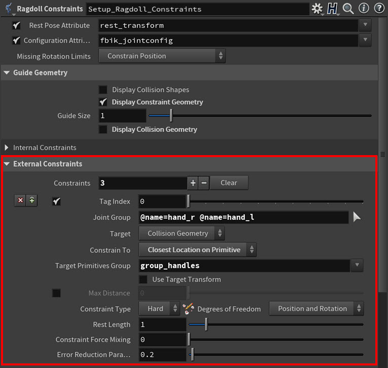
We used hard constraints to pin the hand joints (Joint Group) to the motorcycle handle bars because they strictly constrain position and rotation with no movement, and we used soft constraints to keep the foot and pelvis joints (Joint Group) on the motorcycle because they strongly constrain position and rotation but allow a small amount of movement (as set by Stiffness). We also used the Target Primitives Group parameter for the hand and the foot joints so that their constraints would only look in the specified geometry group for the closest primitives to constrain to.
And finally the
Ragdoll Solver SOP node computes the ragdoll simulation for Erik using the Bullet physics solver.
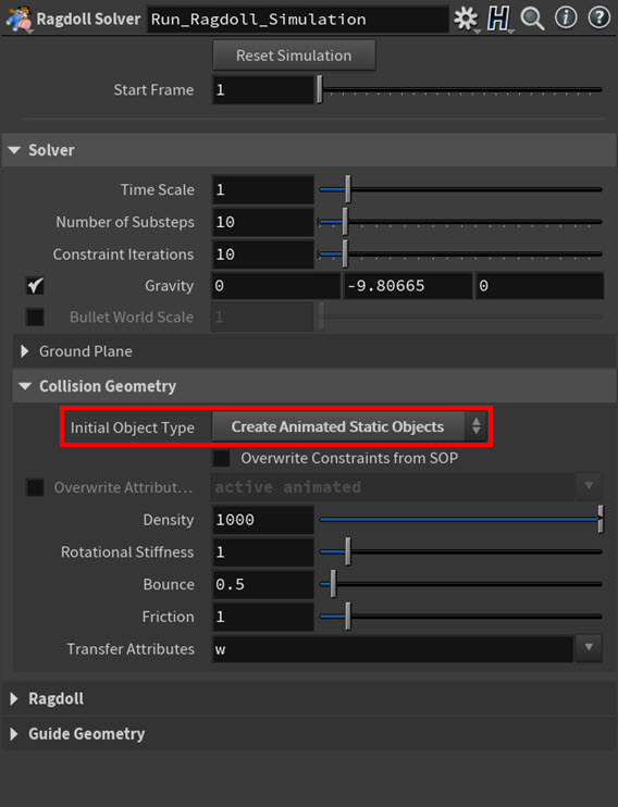
Erik’s Solver settings are all set to the defaults and he does not have a Collision Plane. However, the external collision geometry (the motorcycle) is animated and static, so we wanted its transforms to update at every time step during the simulation but not have the object collide or react to Erik (Collisions Geometry tab ▸ Initial Object Type parameter ▸ Create Animated Static Objects parameter option). Erik can collide against the motorcycle (because of his collision shapes), but the motorcycle is not collidable and it will ignore any objects it comes into contact with.
In the Ragdoll section, the Rest Pose Attribute is set to the rest pose attribute (rest_transform) that was created by
Rig Stash Pose SOP node because Erik needs to be in his rest position before the simulation is solved. The Frame Range is also set to the duration we want for the ragdoll simulation. For Erik, this also corresponds to the duration of the motorcycle’s animation.
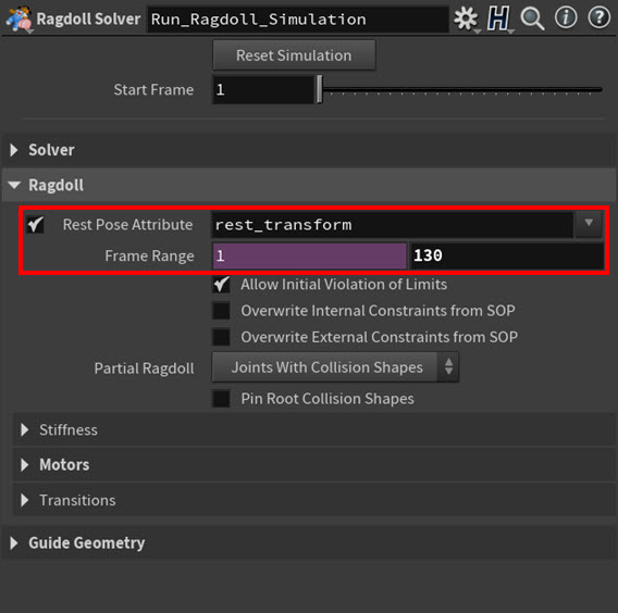
Allow Initial Violation of Limit is turned on to prevent any of Erik’s joints from popping at the beginning of the simulation if they are already outside their rotation limits before the simulation starts. This also makes sure that any joints that are outside their rotation limits when initialized are then encouraged to move towards a rotation in their proper set range.
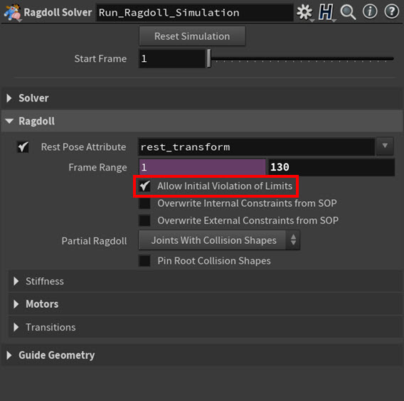
And Partial Ragdoll ▸ Joints With Collision Shapes tells the solver to only run the simulation on the joints that have collision shapes. In many cases, you don’t have to run the ragdoll sim on the entire character’s skeleton since many of the accessory joints come along for the ride anyway.
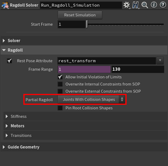
For Erik, the default Stiffness settings are sufficient, but we used Motors for his spine and head joints. For the specified motor joints (Group), the solver tries to constantly (Strength Value ▸ Constant) push those joints towards the transforms dictated by their rest pose (since Erik is not animated) during the solve. This is a way to tell the solver to affect the Group joints with physics, but also try as much (Motor Strength) as it can to keep them true to their original rest positions. This allows Erik to bounce around while maintaining his original posture.
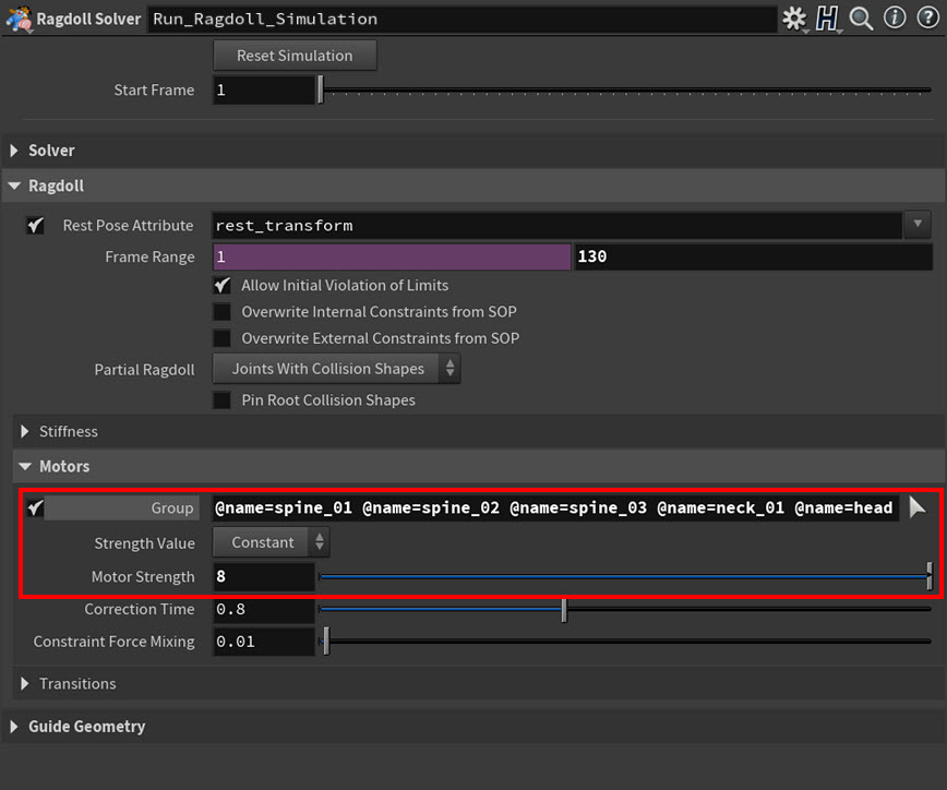
And finally, since Erik’s transition to ragdolling does not depend on specific criteria, Transitions is disabled for him.
Example 2: Ragdoll set-up with external collision geometry and transitions 
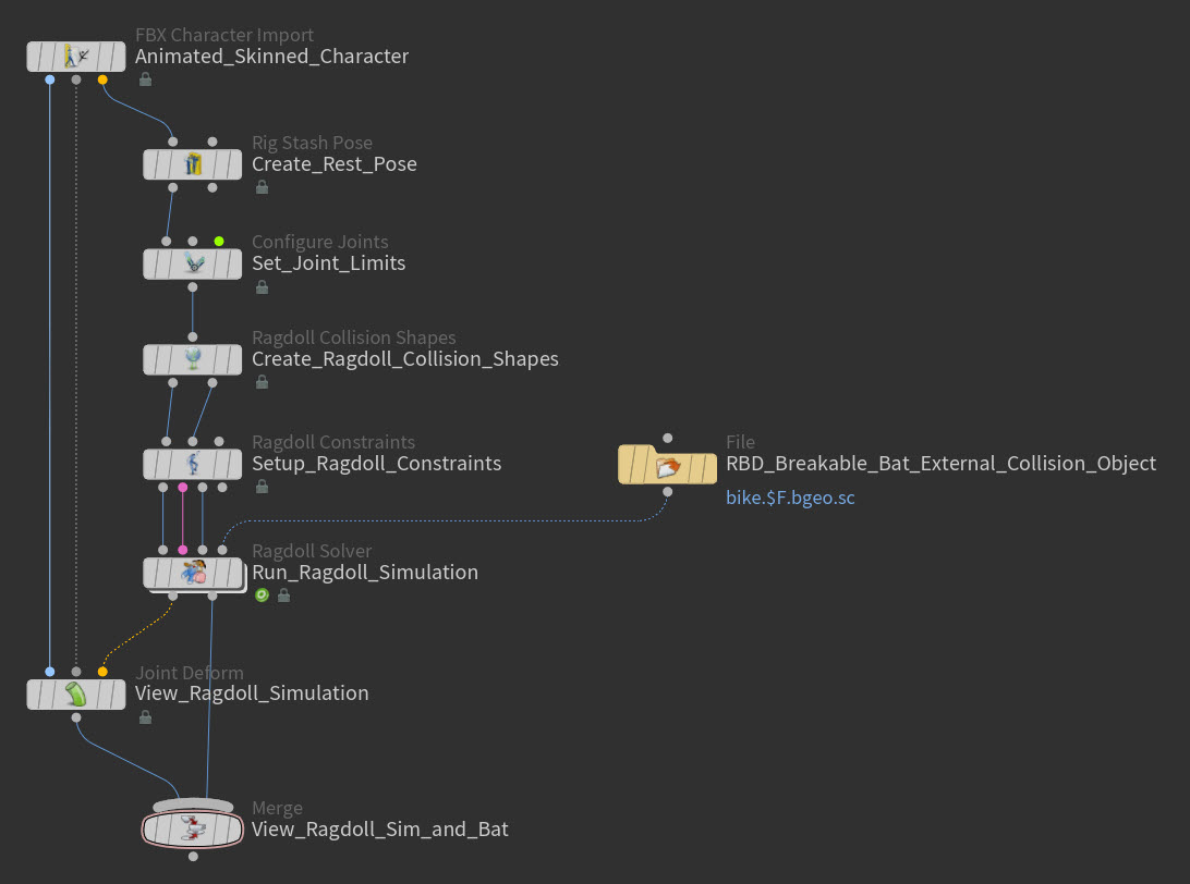
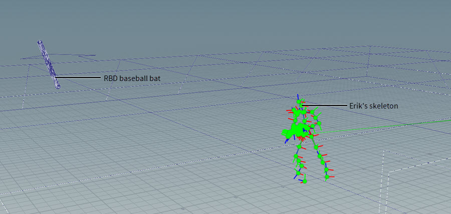
In this example ragdoll set-up, Erik runs forward and is then hit by an RBD baseball bat external collision object. As a result, he is tossed backwards and then lands on the ground plane crumpled in a heap.
For this character, the first thing that is created for Erik is his rest position. This is because Erik needs to be in his rest pose position when we set his joint limits, create his ragdoll collision shapes, set up his ragdoll constraints, and run his ragdoll simulation.
The
Rig Stash Pose SOP node creates the
rest_transform attribute and stores (Mode ▸ Store) Erik’s current pose (just a regular t-pose) as his rest pose (Attribute Name) for the simulation.
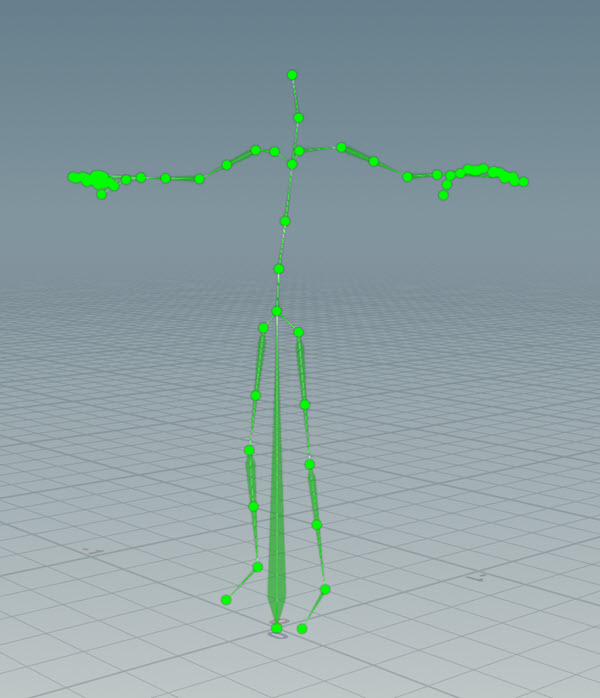

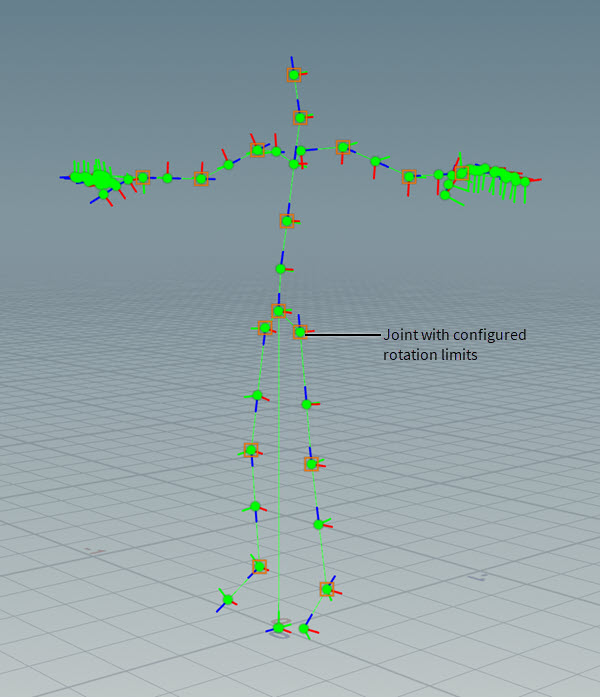
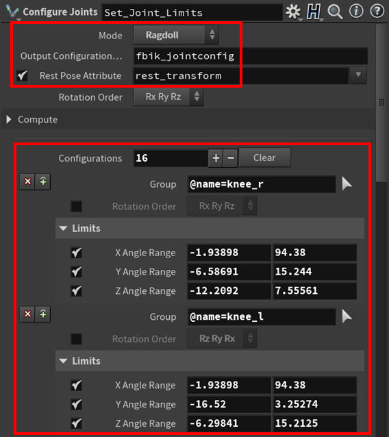
The
Configure Joints SOP node puts Erik’s skeleton in its rest position (Rest Pose Attribute), defines the rotation limits (Configurations multiparms) for the all the major joints in Eric’s skeleton (like the knees, elbows, hips, shoulders, and so on), and then saves those limits to the
fbik_jointconfig attribute (Output Configuration). These limits restrict how far those joints can move from their rest positions during the ragdoll simulation, and they prevent Erik’s limbs or spine from bending at odd angles. Mode is set to Ragdoll because only joint limits for rotation are required for this set-up.
The
Ragdoll Collision Shapes SOP node puts Erik’s skeleton in its rest position (Rest Pose Attribute) and then creates the collision shapes for the ragdoll simulation based on the Collision Shapes multiparm settings. These shapes allow Erik to collide with external collision objects like the RBD baseball bat, but they do not allow the RBD baseball bat to collide with Erik (that collision behavior is set up on the solver).
Tip
If you want to learn how to swap in custom collision shapes for your own ragdoll set-up, see Example 3: Custom collision shape geometry.
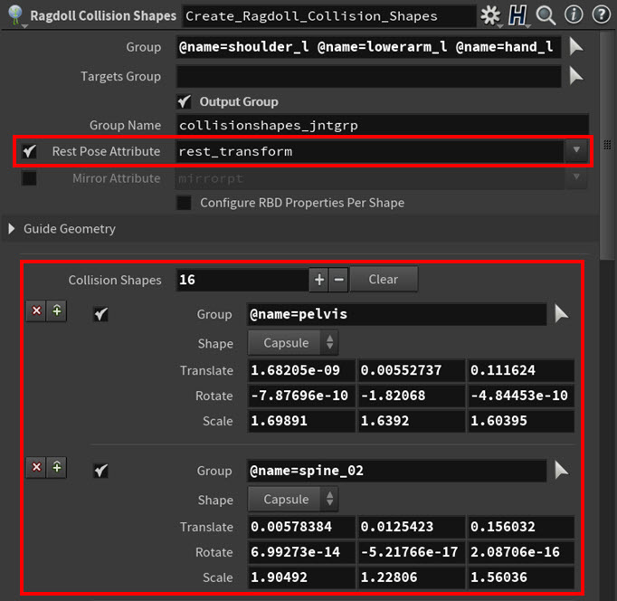
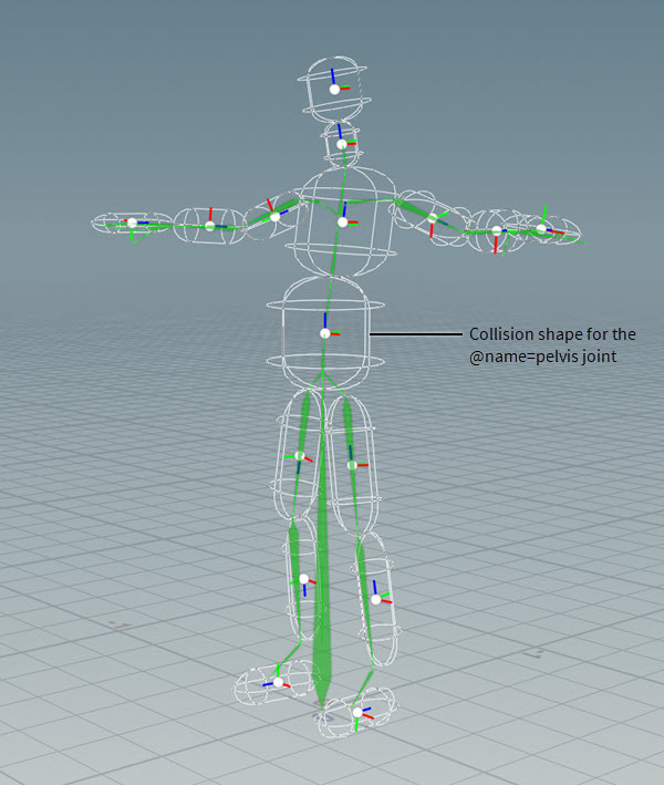
Each collision shape is a simple capsule primitive that is linked to a specific joint (or joints) in Erik’s skeleton. They also follow the general volume of Erik’s model to best represent his topology.
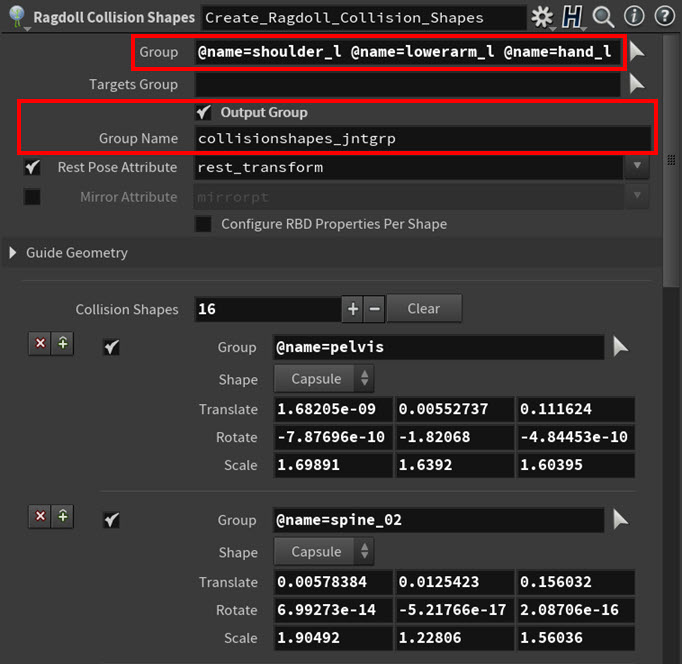
All the joints listed in Group are also output (Output Group) to a point group (Group Name) on the collision shapes.
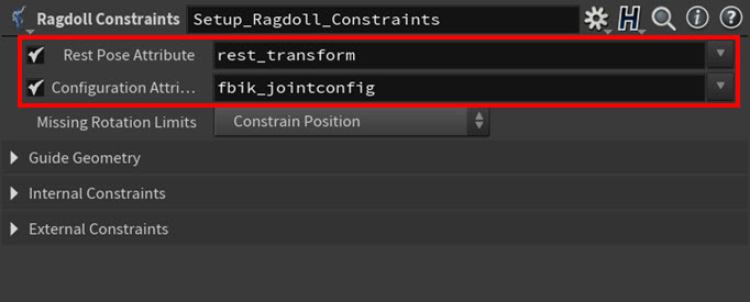
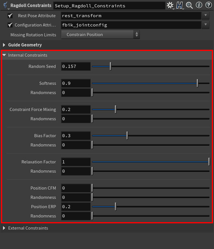
The Ragdoll Constraints SOP node puts Erik’s skeleton in its rest position (Rest Pose Attribute) and then creates an internal constraint for every joint in Erik’s skeleton that has a collision shape using the rotation limits (Configuration Attribute) set up by the
Configure Joints SOP. These ragdoll constraints keep Erik’s body together and his limbs in the right positions during the ragdoll simulation.
Also a cone twist constraint is automatically created (Missing Rotation Limits ▸ Constrain Position) for any joint in Erik’s skeleton that does not have a collision shape.
Erik’s Internal Constraints are set to their default values (the default settings tend to give good results out-of-the-box), and there are no External Constraints defined.
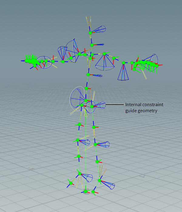
With Guide Geometry ▸ Display Constraint Geometry = on, you can see the internal constraint cone angles (which reflect the joint limits that were set up with the
Configure Joints SOP node).
And finally the
Ragdoll Solver SOP node computes the ragdoll simulation of the swinging baseball bat hitting the running Erik character using the Bullet physics solver. The RBD baseball bat external collision object is supplied on the fourth input of the Ragdoll Solver SOP node.
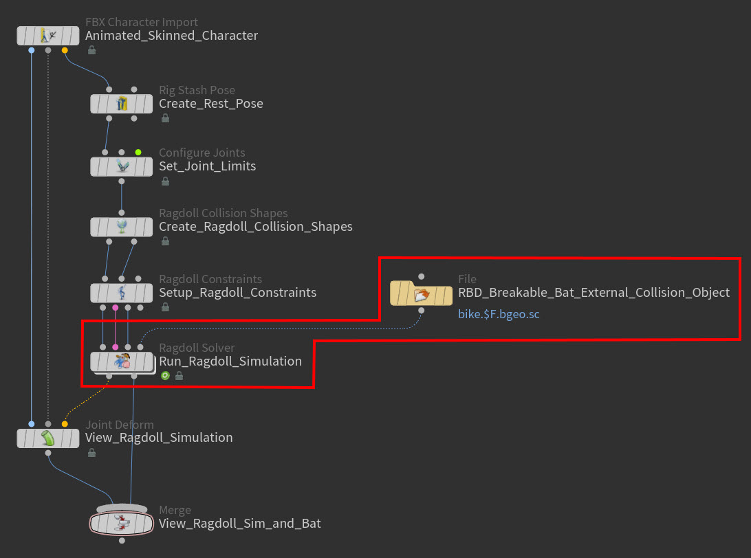
Important Note
Collision geometry must be packed geometry. It can be a normal
Pack SOP or an
RBD Pack SOP. In this example, the RBD baseball bat is made up of three packed geometries, each of which corresponds to a piece that comes out of a material fracture.
The general Solver settings are all set to their defaults, but the Ground Plane is enabled and the Collision Geometry settings are customized.
The Ground Plane settings generate a collision ground plane (Add Ground Plane parameter ▸ Ground Plane parameter setting) under Erik’s feet so that he has a collidable planar surface to both run on as well as fall onto after the RBD baseball bat’s impact.
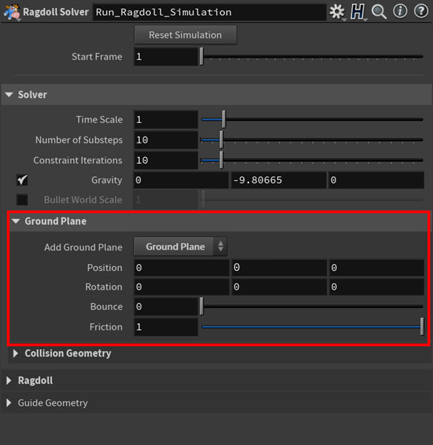
You can view the ground plane in the viewport by turning on the Guide Geometry ▸ Display Ground Plane Geometry parameter.
The Collision Geometry settings makes it so that the RBD baseball bat is included in the simulation and it reacts to Erik during the simulation (Initial Object Type ▸ Create Active Objects). They also make sure that the active and animated attributes (see RBD Packed Object DOP) on the RBD baseball bat are also updated (Override Attributes from SOP) at each frame of its animation.
You can view the collision geometry for your ragdoll simulation (supplied by the fourth input on the Ragdoll Solver SOP node or by the third input on the Ragdoll Constraints SOP node) in the viewport by turning on the Guide Geometry ▸ Display Collision Geometry parameter.
In the Ragdoll section, the Rest Pose Attribute is set to the rest pose attribute (rest_transform) that was created by
Rig Stash Pose SOP node because Erik needs to be in his rest position before the simulation is solved. The Frame Range is also set to the duration we want for the ragdoll simulation.
Allow Initial Violation of Limit is turned on to prevent any of Erik’s joints from popping at the beginning of the simulation if they are already outside their rotation limits before the simulation starts. This also makes sure that any joints that are outside their rotation limits when initialized are encouraged to move towards a rotation in their proper set range.
The Transitions parameters define the criteria (Type ▸ RBD Impact Data) for the activation of the ragdoll and which RBD objects should be considered for impacts (DOP Impact Objects). Erik’s switch to ragdoll is triggered by the magnitude of his impact (Impact Threshold) with the RBD baseball bat. For this example, the external collision object connected to the fourth input on the Ragdoll Solver SOP node (the RBD baseball bat) is automatically given the
collision_object attribute.
And finally, since Erik does not need his posture maintained, or partial ragdolling, or custom stiffness settings, so Partial Ragdoll and Motors are disabled and the Stiffness settings are left at their default values.
Example 3: Custom collision shape geometry 
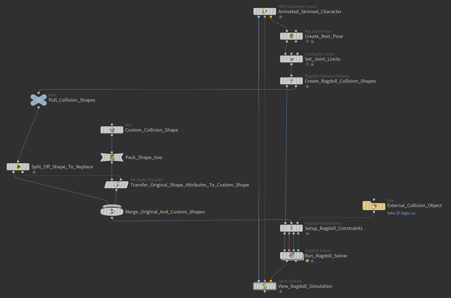
In this example, we will edit an existing ragdoll simulation SOP network to insert a custom collision shape by replacing one of the collision shapes that are generated by the
Ragdoll Collision Shapes SOP node with our own custom primitive.
-
Create a
Null SOP node and connect it to the
Ragdoll Constraints SOP’s second output.
This node will collect the collision shape geometry data.


Null SOP’s collision shape geometry data in viewport -
Create a
Split SOP node and connect its input to the Null SOP’s output.
You will use the Split SOP to pull out a single collision shape so that you can replace it.

-
Select the Split SOP, turn on its display flag, click in the viewport, and then press Enter.
You are now in the Split SOP node’s viewport state.
-
In the Parameter Editor, do the following:
-
Click the arrow next to the Group parameter, in the viewport click the collision shape you want to replace, and then press Enter.
-
Select Group Type ▸ Primitives.
-
Turn on Invert Selection.
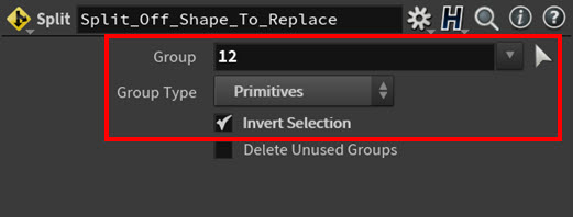
The Split SOP is now only splitting off the one collision object you selected in the viewport.

Split SOP’s collision shape geometry data in viewport -
-
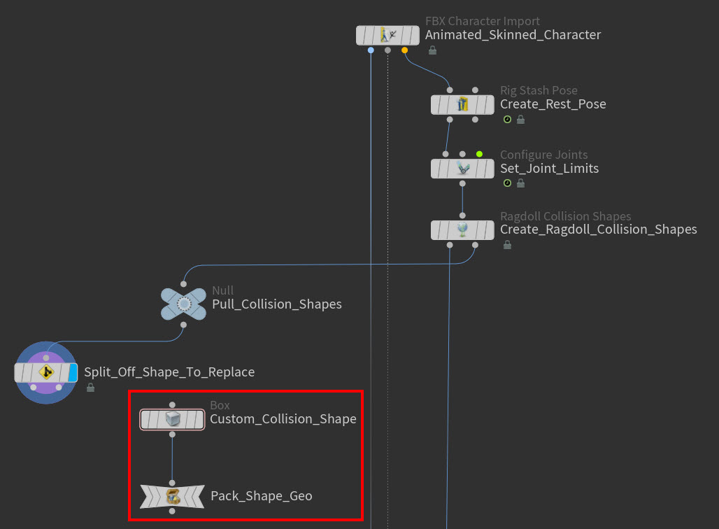
Create your custom collision object. It must be a packed primitive.
In this example, we use a simple
Box SOP and then turn it into a packed primitive with a
Pack SOP node.
-
Create an
Attribute Transfer SOP node and then:
-
Connect the first input on the Attribute Transfer SOP node to the output on the custom shape’s node (if already a packed primitive) or Pack SOP node.
-
Connect the second input on the Attribute Transfer SOP node to the second output on the Split SOP node.
This is the most important step of the process because we need to transfer the attributes from the original collision shape to the new custom collision shape before we can connect it to the
Ragdoll Constraints SOP node.

Important Note
The
Ragdoll Collision Shapes SOP node just creates shapes with attributes. You can replace any of those shapes with your own custom shapes as long as you make sure to transfer the
nameandPattributes from the original shapes to the new shapes that are replacing them. -
-
In the Parameter Editor, adjust the following parameters for the Attribute Transfer SOP:
-
Turn on Primitives.
-
Turn on Points.
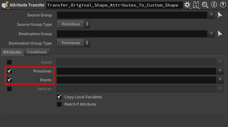
This will ensure the transfer of the
nameandPattributes from the original shape to the new shape. -
-
Create a
Merge SOP and do the following:
-
Connect the first output on the Split SOP node to the Merge SOP.
-
Connect the output from the Attribute Transfer SOP to the Merge SOP.

This merges the geometry data from the original collision shapes with that of the new custom collision shape (the box).

-
-
Connect the output on the Merge SOP node to the second input on the Ragdoll Constraints SOP node.
This brings the collision shape data back to the ragdoll SOP network’s main stream.

-
Select the
Ragdoll Solver SOP node, turn on its display flag, click in the viewport, and then press Enter.
You are now in the Ragdoll Solver SOP's viewport state.
-
In the Parameter Editor, do the following:
-
Click Reset Simulation.
-
In the Guide Geometry section, turn on Display Collision Shapes.
If you can now see your custom collision shape in the viewport, you successfully replaced a regular collision shape with your custom shape.

-