| On this page |
|

To prepare a skeleton for rigging, extra information can be added to the character’s base skeleton to create a reference skeleton, called a guide skeleton. The information on the guide skeleton is then picked up by rig components downstream to help build up the rig functionality of the character.
Guide skeleton 
A guide skeleton is the character’s base skeleton with tags, properties, and other information added to it. Note that a rig is not built for the guide skeleton; we just use the extra information on the guide skeleton to build up the final rig for the character. We refer to the joints on the guide skeleton as guide joints.
Some of the information that could be added to create a guide skeleton are:
-
Extra joints that are used as a reference for creating controls on the rig.
-
Tags (labels) that identify groups of joints.
-
Properties that set information on the guide joints.
Note
A note about terminology: When a skeleton (or guide skeleton) is converted to a rig using the fktranform rig component, the skeleton joints are converted to TransformObject graph nodes in a 1-to-1 mapping. These TransformObject nodes essentially make up the joint hierarchy in APEX, so for ease of understanding, we will refer to the TransformObject nodes as APEX joints.
When at least one transform component (translate, rotate, or scale) on an APEX joint is promoted, the APEX joint becomes a control that the user can interact with in the viewport.
Tags 
Tags are essentially labels that are added on guide joints to identify and group joints. For example, we could tag the shoulder, elbow, and hand joints on the left side of the skeleton with the string L_Arm, which groups these joints as a body part. This tag is then used by rig components downstream to identify groups of joints to apply the rig functionality to. In this way, tags are a way for the skeleton to communicate information to the rig components.
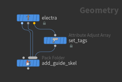
Tags are stored in the tags string array attribute on the guide joints, and are created using the ![]() Attribute Adjust Array SOP. In the network editor, “Attribute Adjust Tags” is an alias to the Attribute Adjust Array SOP.
Attribute Adjust Array SOP. In the network editor, “Attribute Adjust Tags” is an alias to the Attribute Adjust Array SOP.
Note
When you specify tags on joints, the rig components don’t automatically pick them up - you need to update the rig components to fetch the tags. Specify the tags to fetch in the segments parameter in the rig components.
Properties 
Properties are information stored on guide joints that are picked up later by rig components to configure the controls they create. For example, if you want a character’s finger controls to have a box shape, you could set the control shape property for the finger joints in the guide skeleton. When the FK rig component downstream creates controls for the rig, it will pick up this property on the finger guide joints and create box shape controls.
Properties are stored in the properties dictionary attribute on the guide joints, and are created using the ![]() Attribute Adjust Dictionary SOP. The following properties can be set:
Attribute Adjust Dictionary SOP. The following properties can be set:
Property |
Type |
Description |
|---|---|---|
scaleinheritance |
|
The scale inheritance of the APEX joint. |
rord |
|
The rotation order of the APEX joint. |
xord |
|
The transformation order of the APEX joint. |
promote |
|
The transform components to promote on the APEX joint, for example, “t r s”. |
shape |
|
The control shape. You can specify any of the pre-shipped shapes listed in the APEX Configure Controls SOP Shape Override parameter, for example, |
shapetranslate |
|
The position of the control shape. |
shaperotate |
|
The rotation of the control shape. |
shapescale |
|
The scale of the control shape. |
shapecolor |
|
The color of the control shape. |
Adding and using tags 
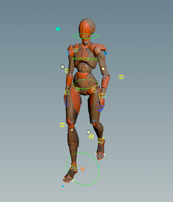
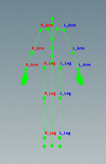
In this example, tags are added to Electra’s arms and legs. These tags are then picked up by the multi IK rig component downstream, which adds IK functionality to the tagged limbs.
Create a guide skeleton with tags 
We first add tags on the ![]() Electra test geometry’s base skeleton to create a guide skeleton:
Electra test geometry’s base skeleton to create a guide skeleton:
-
On the Electra test geometry SOP, set Output to Skin Surface.
-
On the
 Attribute Adjust Array SOP:
-
Set Attribute Class to Point.
-
Set Array Type to String.
-
-
Enter the Attribute Adjust Array viewer state by clicking
 Show Handle on the left toolbar, or hovering over the viewport and pressing Enter.
 -
In the Attribute Adjust Array viewer state, set the tags:
-
Select the joint(s).
-
Press A.
-
Enter a name for the tag.
-
Press Enter.
The multiparm entries in the Set Values section of the Attribute Adjust Array SOP are automatically populated with the tags set in the viewer state.
-
-
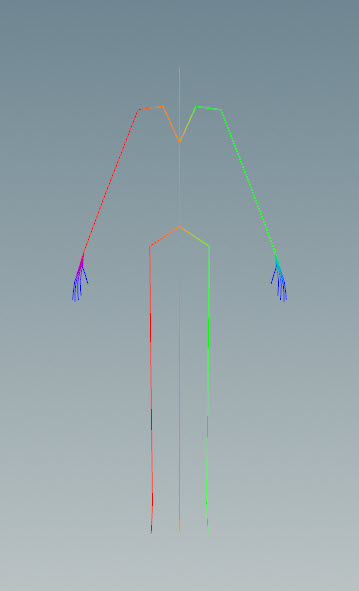
Set different colors for the tags on the two sides of the skeleton:
-
On the Attribute Adjust Array SOP, Visualize section, click
 beside Colorize to add a color for a group of tags.
 -
Set the Value parameter to
L_*. -
Set the color.
-
Repeat for the the right side, with Value =
R_*.
Skeleton tags -
-
Electra’s base skeleton with the added tags is the guide skeleton. The
 Pack Folder SOP adds the guide skeleton back into the set of character files. See the packed character format for more information on how to name the character elements in the character folder structure. On the Pack Folder SOP:
-
1st input is Electra’s skin. Set Name =
Base, Type =shp. -
2nd input is Electra’s base skeleton. Set Name =
Base, Type =skel. -
3rd input is the guide skeleton. Set Name =
Guides, Type =skel.
-
-
To view the tags on the guide joints:
-
Select the Attribute Adjust Array SOP.
-
In the geometry spreadsheet, select
 from the top toolbar.
 -
For the arm and leg joints,
 the entry under the tags column, and select Inspect. The following
 tagsstring array will be displayed for the arm joints:[ L_Arm ]
-
Use skeleton tags in the rig component 
We now use Houdini’s pre-built rig components to build a rig for Electra that includes IK functionality for the arms and legs:
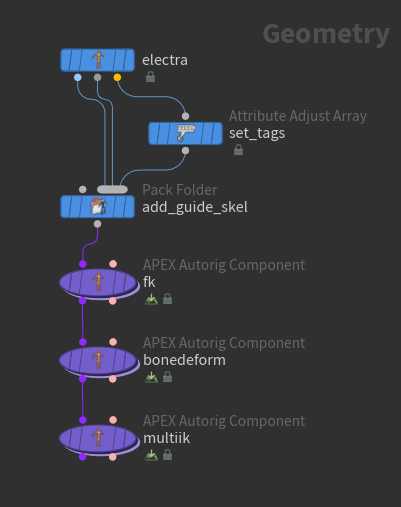
-
We first add FK functionality using the fktransform rig component. The fktransform component converts the skeleton joints into APEX joints. On the
fkAPEX Autorig Component SOP:-
Set Component Source to fktransform.
-
In the Source tab, set skeleton to
Guides.skel. -
In the Controls tab, set tpromotegroup and rpromotegroup to
*. This promotes the translate and rotate components for all the APEX joints so that they can be interacted with in the viewport.
Add FK functionality to the rig -
-
The bonedeform rig component adds the character skin on the skeleton. On the
bonedeformAPEX Autorig Component SOP, set Component Source to bonedeform.Add bone deformation functionality to the rig -
The multiik rig component adds IK functionality to the rig. It can add itself to the rig multiple times by looking for tags on the skeleton joints, and adding itself on those joint groups. On the
multiikAPEX Autorig Component SOP:-
Set Component Source to multiik.
-
In the Driven tab, set segments to
"*Leg *Arm". This tells the multiik rig component to add IK on the guide joints that have*Legand*Armtags.
Add IK functionality to the rig -
Note
In addition to the tags that users can add to create a guide skeleton, rig components can also add tags on controls, APEX joints, and other graph nodes they create. Rig components further down the line can then pick up on these tags and perform their own functionality on specific groups of nodes.
For example, by default, the fktransform component adds the bind tag on all the APEX joints that it creates (set in the tags parameter). Downstream, the multiik component’s driven parameter is set to %tag(bind) by default. This tells the multiik component that any APEX joint tagged with bind is available to have IK functionality applied to it. It then looks at the segments parameter for the tagged joints to actually apply IK to.
Use the same rig for multiple characters 
The IK rig functionality used for Electra can also be applied to a different character, in this case, an elephant:
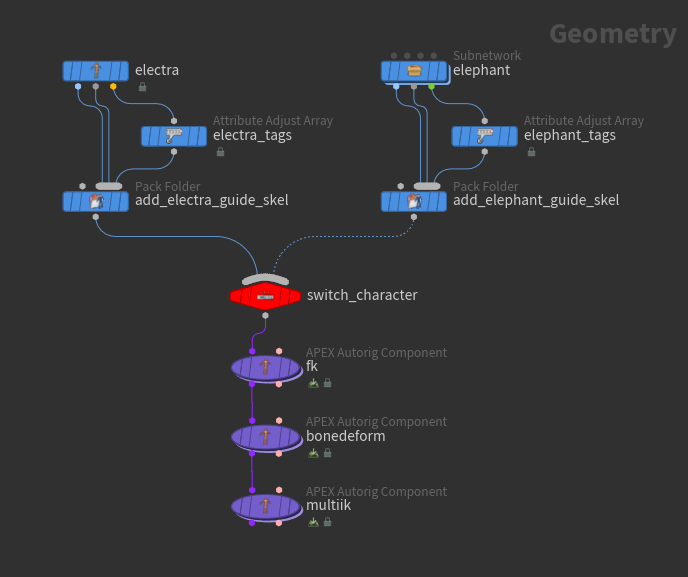
Set tags on the elephant’s legs:
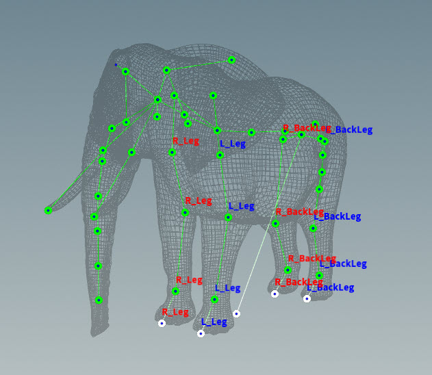
On the multiik rig component, the segments parameter is set to "*Leg *Arm". So for Electra, IK is added on Electra’s arms and legs tagged with *Leg and *Arm. On the elephant, IK is added to the 4 legs tagged with *Leg.
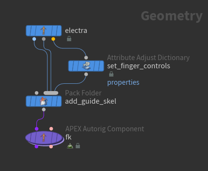
Adding properties to a guide skeleton 
In the previous example, joints were promoted to controls using the fktransform rig component. In the example below, we instead use properties to specify the APEX joints to turn into controls. We also use properties to specify the look of the controls. Properties are created using the ![]() Attribute Adjust Dictionary SOP.
Attribute Adjust Dictionary SOP.
-
On the Attribute Adjust Dictionary SOP:
-
Set Attribute Name to
properties. -
Set Attribute Class to Point.
-
-
Select the skeleton joints to apply the properties to:
-
Click
 beside the Group parameter.
 -
In the viewport, select the finger joints. Hold ⇧ Shift to select multiple joints.
-
Press Enter. The Group parameter will be populated with the point numbers of the selected joints.
Note
If you want to add properties for different sets of joints, you need to use separate Attribute Adjust Array SOPs, with the Group parameter in each SOP set to a different joint group.
-
-
Set the rotation to be promoted for the finger joints. In the Set Values section:
-
Key =
promote -
Type = String
-
Value =
r
Note
To promote multiple components, specify the components in Value separated by a space, for example, “t r s”.
-
-
Set the control shape for the finger joints. In the Set Values section:
-
Add another entry in the properties dictionary by clicking
beside Number of Entries. -
Key =
shape -
Type = String
-
Value =
circle_wires
-
-
Set the size of the finger controls. In the Set Values section:
-
Add another entry in the properties dictionary by clicking
beside Number of Entries. -
Key =
shapescale -
Type = Vector3
-
Value = (0.2, 0.2, 0.2)
-
-
To view the properties on the guide joints:
-
Select the Attribute Adjust Dictionary SOP.
-
In the geometry spreadsheet, select
from the top toolbar. -
For the finger joints,
the entry under the properties column, and select Inspect. The following propertiesdictionary will be displayed:"promote":"r", "shape":"circle_wires", "shapescale":[0.2,0.2,0.2]
-
-
On the
fkAPEX Autorig Component SOP:-
Set Component Source to fktransform.
-
In the Source tab, set skeleton to
Guides.skel. -
In the Controls tab, clear the tpromotegroup, rpromotegroup, and spromotegroup parameters, so that the fktransform component itself does not promote any of the joints to controls.
-
-
View the control properties that are picked up by the fktransform component. Select the
fkAPEX Autorig Component SOP, and press Enter over the viewport.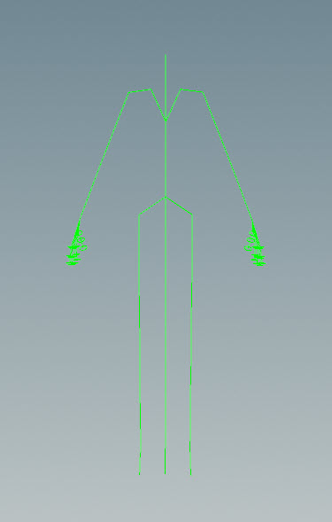
Finger controls on the rig
Adding extra joints to the guide skeleton 
Extra joints can be added to the guide skeleton using a ![]() Rig Attribute VOP SOP. These joints can then be used later as a reference for creating controls on the rig. In this example, the added joint is used downstream in a lookat rig component:
Rig Attribute VOP SOP. These joints can then be used later as a reference for creating controls on the rig. In this example, the added joint is used downstream in a lookat rig component:
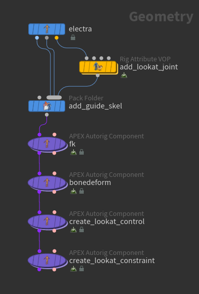
Add a lookat joint to the guide skeleton 
-
Set the display flag on the Rig Attribute VOP SOP.
-
Double-click the Rig Attribute VOP SOP to enter the node.
-
Enter the Rig Attribute viewer state by clicking
Show Handle on the left toolbar, or hovering over the viewport and pressing Enter. -
Drag the head joint to the network view to automatically create a
 Get Point Transform VOP, which represents the transform of the head joint. This head joint is used as a reference for creating the lookat joint.
Get head joint -
Add an
 Offset Transform VOP and
  Add Joint VOP:
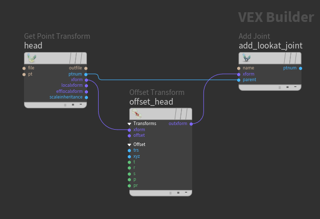
Add lookat joint to guide skeleton -
Set the position of the lookat joint by adjusting the Translate parameter on the Offset Transform VOP.
-
On the Add Joint VOP, set Name to
lookat_locator. -
Parent the lookat joint to the head - connect Get Point Transform VOP ptnum → Add Joint VOP parent.
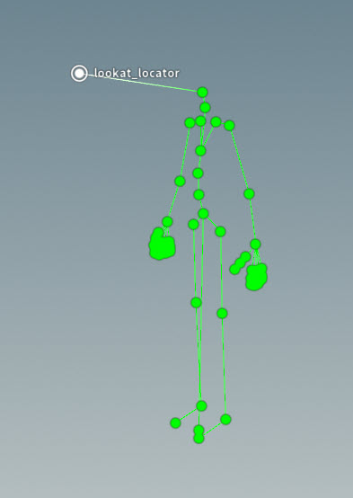
Lookat joint added to guide skeleton
Create the lookat control 
We now create a control at the position of the lookat joint:
-
On the
Pack Folder SOP:-
1st input is Electra’s skin. Set Name =
Base, Type =shp. -
2nd input is Electra’s base skeleton. Set Name =
Base, Type =skel. -
3rd input is the guide skeleton. Set Name =
Guides, Type =skel.
-
-
On the
fkAPEX Autorig Component SOP:-
Set Component Source to fktransform.
-
In the Source tab, set skeleton to
Guides.skel. -
Promote the root joint, and the rotate component of the head joint. In the Controls tab:
-
Set tpromotegroup to
root. -
Set rpromotegroup to
root head.
-
-
-
On the
bonedeformAPEX Autorig Component SOP, set Component Source to bonedeform. -
Create the control for the lookat joint. On the
create_lookat_controlAPEX Autorig Component SOP:-
Set Component Source to transformdriver.
-
In the Settings tab, turn off use_t, use_r, and use_s.
-
In the Driven tab, clear the driventransforms parameter.
-
In the Control tab:
-
Set driver to
lookat_ctrl. This is the name of the lookat control. -
Set driverguide to
lookat_locator. This is the position to place the lookat control. -
Set driverparent to
root, which parents the lookat control to the root joint.
-
-
In the Shape tab:
-
Set shape to
ball. -
Increase the scale of the shape.
-
Lookat control -
Create the lookat constraint 
On the create_lookat_constraint APEX Autorig Component SOP:
-
Set Component Source to lookat.
-
In the Settings tab, set updir to (0, 0, -0.3). This places the up vector above the head joint.
-
In the Driven tab:
-
Set driven to
head. -
Set driver to
head_ctrl. This is the name of the control created by the lookat component that allows you to move the driven joint. -
Set target to
lookat_ctrl. -
Set up to
head_up. This is the name of the control for the up position. -
Turn on useup.
Lookat constraint -
Adding colors to the guide skeleton 
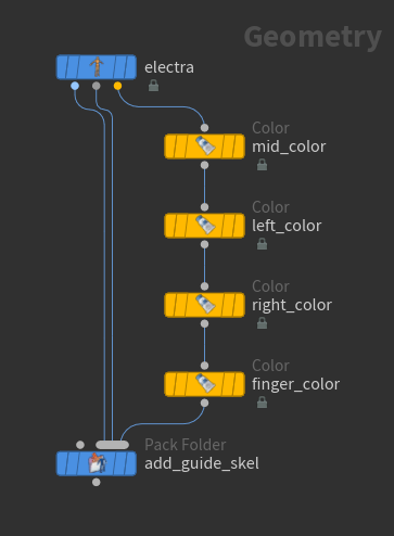
On each of the ![]() Color SOPs:
Color SOPs:
-
Set Group Type to Points.
-
Specify the joints to apply the color to:
-
Click
beside the Group parameter. -
In the viewport, select the joints. Hold ⇧ Shift to select multiple joints.
-
Press Enter. The Group parameter will be populated with the point numbers of the selected joints.
-
-
Set the Color.
Colors on guide skeleton
How-to 
| To... | Do this |
|---|---|
|
Remove a tag from a joint |
In the Attribute Adjust Array viewer state:
|
Content library examples 
The following examples are available in the content library:
|
Learn how to add tags to an Electra skeleton and create a rig for Electra using pre-built rig components. Download the file here. |
|---|---|
|
Easily switch between different character rigs based on the tags added to each character’s skeleton. Download the file here. |