| On this page |

APEX (All-Purpose EXecution) is a graph evaluation framework that builds and runs graphs, and outputs their results. In KineFX, character rigs are represented using APEX graphs.
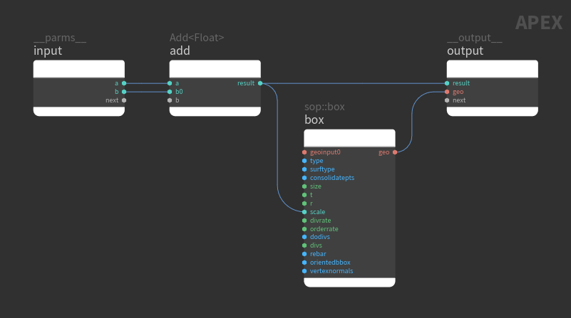
A graph is a piece of logic that, when evaluated, performs a specific task. Graphs can be built up to perform more complex functionality like determining how an entire character behaves, complete with an FK hierarchy for the skeleton, and logic to deform geometry. Graphs take in data in the form of input parameters, perform operations on the data, and make data available as outputs. Within a graph, geometry can be manipulated alongside other types, so you can, for example, perform numerical operations on skeleton joint transforms all in one graph:
In the SOP context, APEX graphs are a piece of geometry. The rig logic represented by an APEX graph is built up in the SOP network as the graph is passed from SOP node to SOP node, with pieces of logic added to or changed on the graph along the way. When building of the graph is complete, the rig logic is evaluated at a point in the network of your choosing (using the APEX Invoke Graph SOP or Python SOP), or through a specific action in the viewport.
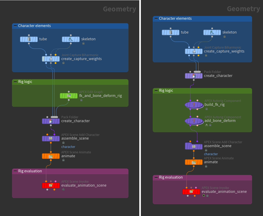
This idea of delayed evaluation of the rig logic allows you to procedurally build up rig logic pieces and assemble them together without having the rig constantly evaluating and calculating, which significantly impacts performance. Delayed evaluation also allows you to choose when and where to evaluate the rig. The example below shows two different ways that rig logic can be added to a character. In both cases, there is a clear delineation between the rig logic and rig evaluation:
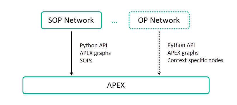
APEX sits at a layer below SOPs and is not tied to any network context. You can build, manipulate, and run APEX graphs using the Python API, other APEX graphs, and SOPs. In the future, there may be other contexts that can access and utilize APEX graphs.
Note
For users who are familiar with VOPs and VEX, APEX is a mid-level visual programming framework - higher than VEX and lower than SOPs. In VOPs, we are limited to the types that VEX understands. APEX is essentially procedural VOPs with support for more types (via an extensible type system).
The type of data that APEX graphs can output is limited only by the context within which the graph is run. When run in SOPs, graphs can output geometry, as well as any data that can be stored in a dictionary attribute on the geometry. When run in Python, graphs can output the types that can be cast to a Python type.
Visualizing graphs 
The APEX network view is a UI that is used to visualize APEX graphs. To open the APEX network view, click the New Tab icon at the top of a pane and select New Pane Tab Type ▸ Animation ▸ APEX Network View. You can also manually build a graph in the APEX network view while on an
APEX Edit Graph SOP. See graphs for numerical operations for some examples.
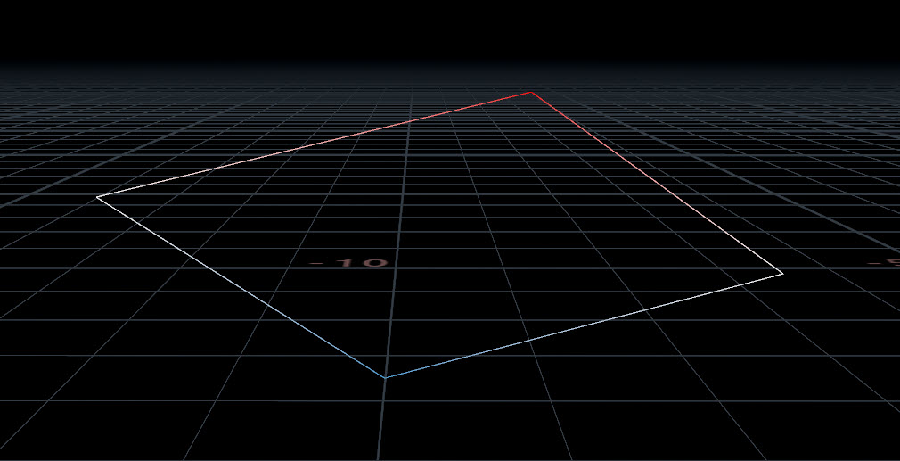
The structure of a graph is represented as geometry, where the graph nodes are represented as points in the viewport, and the connections between the nodes are represented as lines between the points. In the example below, the positions and colors of the graph nodes and their connections directly correlate to the points and lines in the viewport:
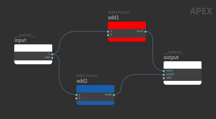
When the positions and colors of the graph nodes change, this is reflected in the viewport geometry:
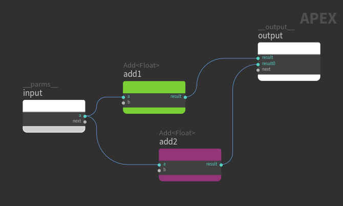
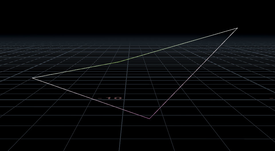
The components of the graph and geometry have the following correlation:
Graph (visualized in the APEX network view) |
Geometry (visualized in the viewport) |
|---|---|
|
Points |
|
Wires |
Line primitives |
Input and output ports on connected nodes |
Vertices |
Input parameters on the graph input node |
Parameters stored on the geometry |
Graph nodes, subgraphs, and subnets 
Graph nodes perform a specific operation and can be APEX functions, verbs, subgraphs, or subnets.
APEX functions
APEX functions perform a specific operation on whatever is connected to its input ports.
Verbs
A verb is the basic operation of an OP node. It does not include other operations that relate to the node like caching, reading inputs, and evaluating parameters. For example, the Joint Deform SOP is an HDA wrapper around the bonedeform verb, so Joint Deform cannot be used in APEX graphs, but bonedeform can.
Subgraph
A subgraph is a locked graph and is similar to an HDA in that modifying a subgraph modifies all instances of the subgraph. The SmoothIk node is an example of a subgraph.
Subgraphs are stored as a subgraph library in a .bgeo geometry file. A subgraph library has the following structure:
-
A single unpacked APEX graph, where the subgraph name is defined by the
namedetail attribute.or
-
A number of packed geometry primitives, each containing an APEX graph. For each of the primitives, the subgraph name is defined by the top-level
nameprimitive attribute.
The subgraph .bgeo files are loaded from the @/apexgraph directories, where @ expands to the directories in the HOUDINI_PATH.
Subnet
A subnet is a container that encapsulates multiple graph nodes inside a single node. Subnets help to simplify and improve the readability of a graph. If you create several subnets with the same contents, updating one of the subnets will not affect the others.
| To... | Do this |
|---|---|
|
Save an unpacked graph to a subgraph library file |
When saving an unpacked APEX graph to a subgraph library file, a 
To load the saved subgraph:
|
|
Save packed graphs to a subgraph library file |
Use a 
To load the saved subgraphs:
|
|
Update all subgraph instances |
After making changes to a subgraph, update all the subgraph instances by doing the following:
|
|
Create a subnet |
|
|
Change the port name of a subnet |
Dive into the subnet and change the port name on the graph input or output node. Rename ports by Note Only subports can be renamed. “Regular” ports cannot be renamed. Subports are created when connections are made to variadic ports. See ports for more information. |
Ports 
Connections between nodes are made when wires are created between the ports on the nodes. Port values come from either port connections, the values set in the node parameter window, or certain default values. The node parameter window is used for editing the port’s values in the APEX network view. To bring up the node parameter window, select a graph node and press P.
Port |
Value |
|---|---|
Connected ports |
Values from connections override the values set inside the node parameter window. |
Unconnected ports |
Unconnected port values come from either the values set in the node parameter window, the corresponding SOP verb node, or default values set internally in APEX. 
Ports that appear in the node parameter window with a black background are present in the geometry spreadsheet
Ports that appear in the node parameter window with a gray background are not present in the
Note The values displayed in the node parameter window are not always the values used by the ports. If a port is not present in the geometry spreadsheet |
Different port colors refer to different data types on the port. There are also two special types of ports - variadic ports and in-place ports:
Variadic port
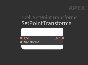
Multiple connections can be made to a variadic port, which creates subports on the node. The port next is an example of a variadic port that exists on several nodes. Other examples of variadic ports are the b port on the Add node, and the transforms port on the skel::GetPointTransforms and skel::SetPointTransforms nodes.
Note
Only subports can be renamed. “Regular” ports cannot be renamed. Rename subports by clicking the subport name.
In-place port
The value of in-place ports are updated without creating a copy. In-place ports are identified with a square:
How-to 
| To... | Do this |
|---|---|
|
Change the parameter values on a graph node |
Select a graph node and press P to bring up the node parameter window. |
|
Rename a subport on the graph |
|
|
Keep a particular graph visible in the APEX network view |
Click the Unpin the graph if you want the APEX network view to follow the SOP node selection in the network editor. |
|
Lay out the graph nodes |
Connect your graph (for example, the |
|
Delete a wire on the graph |
Hold Y and or Select the wire and press Delete. |