| On this page |
|

The animate state provides several convenient options for posing characters in your animation scene, and manipulating the motion path of controls. Tools are also available for adding constraints, dynamic motion, and ragdoll simulations to your animation.
Posing 
Copying and pasting controls 
The copy and paste functionality for controls is accessed through the following options in the ![]() context menu:
context menu:
Copy Selection
Copies the selected controls to the clipboard.
Paste World Transforms
Moves the selected controls to the world position of the controls that were copied with the Copy Selection option. The paste operation tries to match up the control names that are copy/pasted.
If multiple controls are selected with Copy Selection, and the paste operation is not able to match up the control names between the copy and paste operations, the selected controls for the paste operation is moved to the position of the primary control from the Copy Selection. The primary control is the control on which the transform handle is placed during the copy operation.
Paste Local Transforms
Performs the same local transforms on the selected controls as was done on the Copy Selection controls. The paste operation tries to match up the control names that are copy/pasted.
If multiple controls are selected with Copy Selection, and the paste operation is not able to match up the control names between the copy and paste operations, the selected controls for the paste operation is moved to the local position of the primary control from the Copy Selection. The primary control is the control on which the transform handle is placed during the copy operation.
Mirroring poses 
In the animate state, you can mirror the position, rotation, and scale of controls. To mirror controls on a single character or on multiple characters:
-
Select the control(s) you want to mirror. Hold ⇧ Shift or box select to select multiple controls.
-
 click in the viewport and select Mirror with Default or Mirror with Plane:
-
Mirror with Default mirrors the selected controls across the same plane that the rig is mirrored across without any additional user input. The plane that the rig controls are mirrored across is determined in the rig setup.
-
Mirror with Plane puts you in the mirror pose state, where you can adjust the mirror plane. Press ⌃ Ctrl + G to bring up a HUD with the mirror settings, which allow you to set certain configurations before mirroring is applied. Press Enter while hovering over the viewport to apply the mirroring.
-
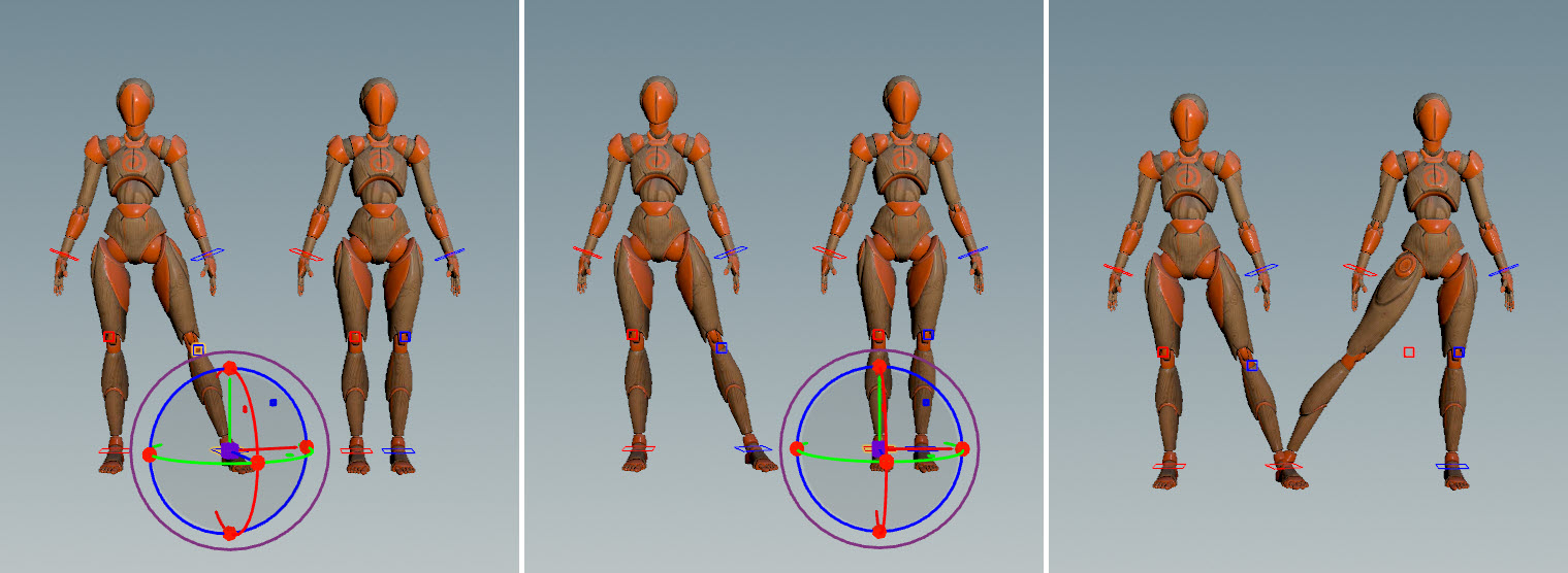
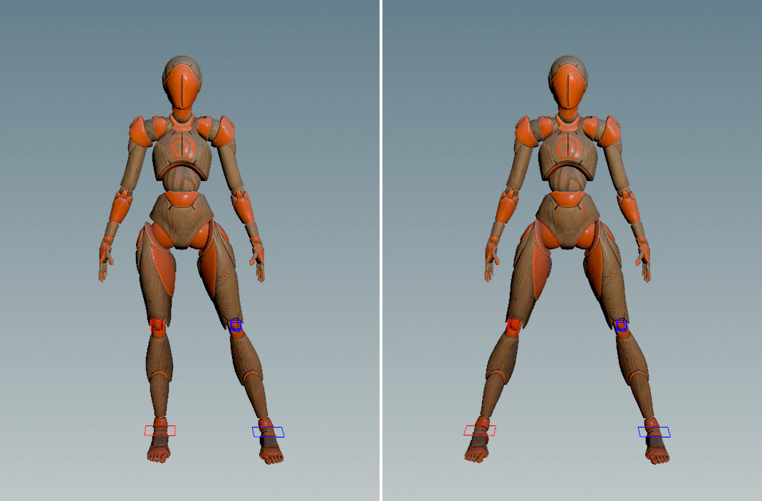
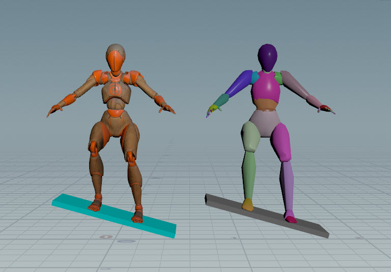
In the example below, Electra’s leg controls (left image) are mirrored to the other side of the rig (right image).
For singular controls that don’t have an equivalent control on the other side of the rig (for example, the spine and chest controls), mirroring is performed by flipping the control across the mirror plane:
Note
By default, the mirroring operation expects the mirrored controls on the rig to be named <control>_l and <control>_r. If the controls are not named in this way, the ![]() APEX Configure Character SOP can be used to specify how the controls on the rig are named, and this information is then used in the mirroring operation. See the How-to for information on how to do this.
APEX Configure Character SOP can be used to specify how the controls on the rig are named, and this information is then used in the mirroring operation. See the How-to for information on how to do this.
Mirror settings 
The mirror settings allow you to set configurations for the mirroring operation. To bring up the mirror settings:
-
Select the control(s) you want to mirror. Hold ⇧ Shift or box select to select multiple controls.
-
click in the viewport and select Mirror with Plane.
-
Press ⌃ Ctrl + G to bring up the settings HUD.
-
Select the Mirror Settings tab.
Setting |
Description |
|---|---|
Flip Axes |
Use this option to fix strange rotations when mirroring. |
Mirror to Opposite Control |
When turned on, performs mirroring on the opposite control. When turned off, performs mirroring on the currently selected control. |
Move Planes Together |
This option is only available when controls on multiple characters are selected. When turned on, moves the mirror planes on the multiple selected characters together. |
Rig Mirror Plane |
The plane within the rig that the controls are mirrored across when the character is at rest position. |
Components |
The tranform components to mirror - translate (T), rotate (R), and scale (S). |
Selection Mode |
The controls that are selected after mirroring. Original The originally selected controls remain selected after mirroring. Mirrored The mirrored controls are selected after mirroring. All Both the originally selected controls and mirrored controls are selected after mirroring. |
Live Preview |
When turned on, shows a live preview of the mirroring performed. |
Outline Overlay |
When turned on, shows a live preview of the mirroring as an overlay layer. Note When mirroring singular controls, turn on the Outline Overlay option. Using Live Preview without Outline Overlay does not work well with singular controls, as singular controls are itself mirrored, which results in the display of the rig switching between the original control position and the mirrored result every time the control is moved. |
How-to 
| To... | Do this |
|---|---|
|
Specify how the controls on the rig are named |
Use the The APEX Configure Character SOP takes in a packed character: 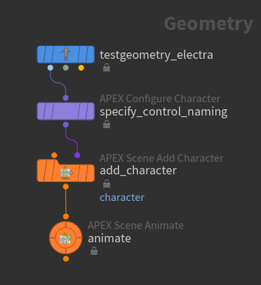
For example, if the rig has controls named like
The mirror pattern is stored in the detail attribute 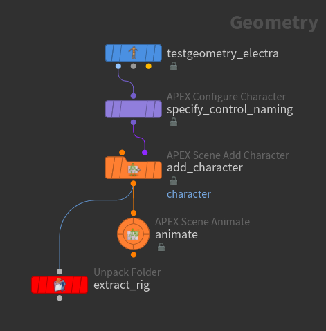
The controls named with the Note If there is no |
|
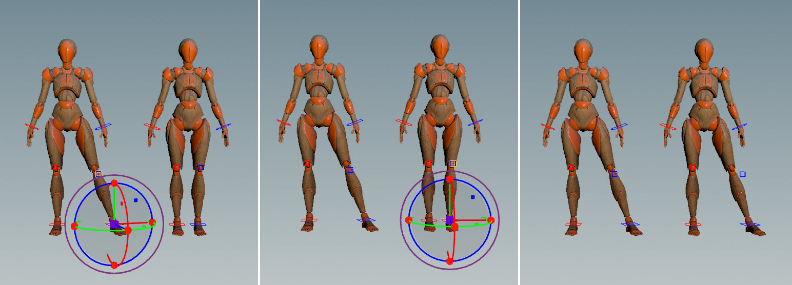
Swap the poses on the two sides of a character |
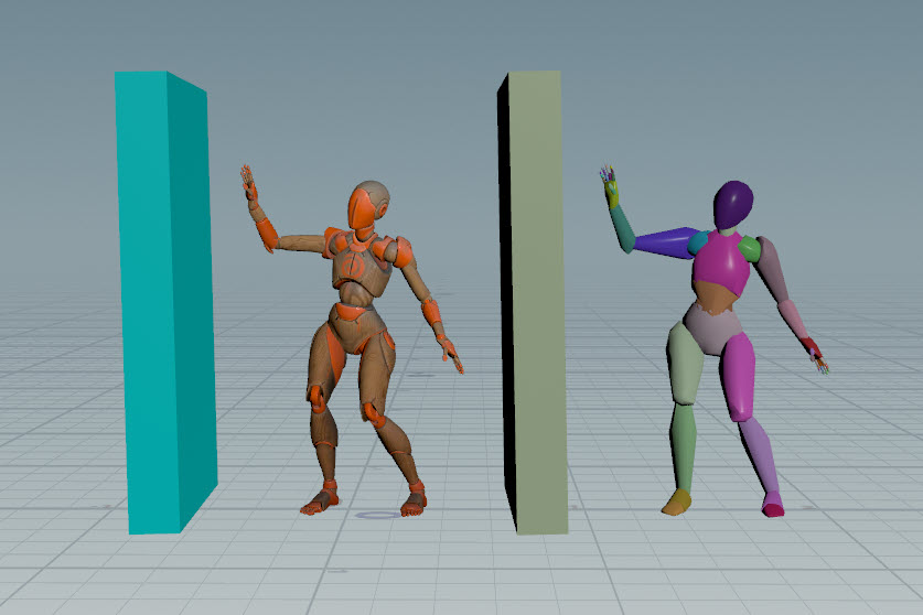
The example below displays the original pose (left image) and the swapped pose after mirroring (right image). 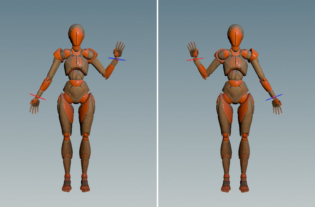
|
|
Perform mirroring on the selected control |
|
|
Mirror a character in world space |
|
|
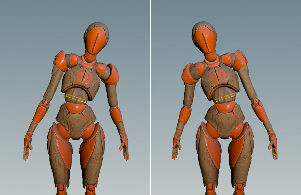
Mirror the control position while keeping the original orientation |
In the example below, only the position of Electra’s hand is mirrored. The rotation of Electra’s right hand remains unchanged. 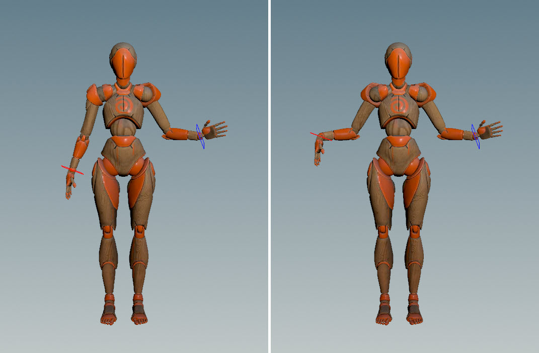
|
|
Mirror across a joint |
|
|
Change the live preview options |
In the settings HUD, Mirror Settings ▸ Advanced tab, set the Live Preview and Outline Overlay options. |
|
Adjust the planes of multiple characters |
|
|
Fix strange rotations when mirroring |
In the mirror settings, try selecting different axes in the Flip Axes option. |
|
Override the plane that the rig controls are mirrored across |
The mirroring operation expects the controls on the rig to be mirrored across the YZ plane. This is the default rig mirror plane. If the controls are mirrored across a non-YZ plane on the rig, this must be specified in one of two ways:
Note The rig mirror plane is the plane that the controls are mirrored across within the rig. The mirror plane is the plane that is used to perform the mirroring operation in the animate state. You should not change the Rig Mirror Plane value in the mirror settings to set the position/orientation of the plane for mirroring. Use the mirror plane handle in the viewport for the mirroring operation instead. |
|
Specify the controls that are selected after mirroring |
In the mirror settings, Advanced tab, set the Selection Mode option. |
|
Move the mirror plane back to the local rig plane |
|
Locators 
A locator is an element that is added to the animate state for use as a pivot point for rotating groups of controls. It can be used to perform FK-type posing for a character. A locator is not part of the rig.
Locators are created using the Add Locator tool, which can be accessed by clicking ![]() Add Locator on the top toolbar, or selecting Add Locator from the radial menu (press C over the viewport).
Add Locator on the top toolbar, or selecting Add Locator from the radial menu (press C over the viewport).
| To... | Do this |
|---|---|
|
Create a locator as a pivot |
Place your mouse over the desired locator position and press H. |
|
Rotate about a locator / Perform FK-type posing |
Note If you don’t hold ⌃ Ctrl + ⇧ Shift when rotating groups of controls, all the controls will rotate about their local axes. See global transform mode. |
|
Change the size and shape of a locator |
⇧ Shift + |
|
Change the color of a locator |
|
Motion paths 
Motion paths allow you to visualize the motion of controls as curves in 3D space, and alter the curves in the viewport. Options for motion paths can be set in the settings HUD, Animate Settings ▸ Motion Path tab.
To display the motion path for a control:
-
Select the control in the animate state.
-
In the settings HUD, Animate Settings ▸ Motion Path tab, click Bind. The motion path for the control is displayed, and the keys on the control are displayed as dots on the motion path. These dots are the motion path controls.
To display the entire motion path, turn off Limit Number of Frames. You could also control the visibility of the motion path using selection sets - the motion path is found in All Controls ▸ motionpath.
Note
A motion path can only be displayed for one control at a time.
-
Move the motion path around by selecting the motion path controls and adjusting the handle:
Motion paths
| To... | Do this |
|---|---|
|
Create a motion path for a control |
|
|
Remove a motion path |
In the settings HUD, Animate Settings ▸ Motion Path tab, click Unbind. |
|
Move the motion path |
Select the motion path control(s). A transform handle is displayed, which can be manipulated to move the selected keys on the motion path. |
|
Display the entire motion path |
In the settings HUD, Animate Settings ▸ Motion Path tab, turn off Limit Number of Frames. |
|
Limit the number of frames shown on the motion path |
In the settings HUD, Animate Settings ▸ Motion Path tab, turn on Limit Number of Frames, and adjust the Frames Before and Frames After values. |
|
Turn on/off the display of the motion path |
In the selection sets HUD/pane:
|
|
Change the size of the motion path ticks |
In the settings HUD, Animate Settings ▸ Motion Path tab, adjust the Path Width. |
|
Change the size of the motion path controls |
In the settings HUD, Animate Settings ▸ Motion Path tab, adjust the Key Size. |
Constraints 
Constraints create a parent-child relationship between controls, where the child control follows the parent control. Two types of constraints can be created in the animate state - transient constraints and regular constraints.
Transient constraints
Transient constraints can be dynamically updated within an animation scene.
Regular constraints
Regular constraints are used for controls that are intended to be constrained for the entire animation scene.
Transient constraints 
Options for transient contraints can be set in the settings HUD, Animate Settings ▸ Transient Constraints tab.
In this example, we want to transfer the ball from one hand to another. The original animation is shown below:
-
Constrain the ball to the hand:
-
Select the driven object (ball), hold SHIFT, then select the driver (hand).
-
On the timeline, select the range of frames to make the constraint active (hold SHIFT and drag on the timeline).
-
Hover over the viewport and press A.
The constraint is created between the ball and the hand, and the keys for the ball are baked to every frame in the selected frame range.
Note
The constraint behavior is only active within the transient constraint frame range.
Constrain ball to hand An arrow visualizer shows the constraint relationship between the ball and hand:

Transient constraint visualizer -
-
Fix the position of the ball on the hand.
Once the transient constraint is created, the driven object (ball) can be moved around, and the changes are automatically applied to the entire frame range that the transient control is active. Make sure you are currently within the frame range that the transient control is active, or the changes will not be applied to the entire frame range.
Note
If the changes are not applied to the entire transient control frame range, make sure that Auto Update Follow Ranges is turned on in the settings HUD, Animate Settings ▸ Transient Constraints tab.
Move driven object (ball) -
Constrain the ball to the other hand.
Ball contrained to both hands at different frame ranges -
Fix the ball on the second hand.
Fix ball on second hand -
Fix the pop on the animation as the ball transitions from one hand to the other.
Animation pop -
Select the ball (driven object).
-
Click in the timeline so that the current frame is within the frame range of the first transient constraint.
-
In the settings HUD, Animate Settings ▸ Transient Contraints tab, click the
 button. This updates the offset on the ball to match the frame after the current contraint range so that there is a smooth transition between the current range and the next range.
Match offsets between contraint ranges -
-
Fix the hand on the first constraint range without moving the ball. Select the hand (driver), hold ⇧ Shift + A, and adjust the hand.
Adjust the hand (driver)
| To... | Do this |
|---|---|
|
Add a transient contraint |
|
|
Remove a transient contraint |
|
|
Adjust the driver object |
Hold ⇧ Shift + A and move the driver object. |
|
Adjust the driven object to match the offsets of an adjacent constraint frame range |
|
|
Update the existing keys when adding a constraint |
The keyframes within the selected range of frames is updated with the constraint behavior. |
|
Add keys to every frame in the constraint frame range when adding a constraint |
Keyframes are added to every frame in the selected frame range. |
|
Turn off display of the constraint visualizer |
In the settings HUD, Animate Settings ▸ Transient Contraints tab, turn off Show Constraint Visualizer. |
Regular constraints 
Regular (non-transient) constraints are created and updated in the Add Constraints tool, which can be accessed by clicking ![]() Add Constraint on the top toolbar, or selecting Add Constraint from the radial menu (press C over the viewport).
Add Constraint on the top toolbar, or selecting Add Constraint from the radial menu (press C over the viewport).
| To... | Do this |
|---|---|
|
Add a constraint |
In the below example, the right hand initially comes off the pole. Once a constraint is added, the right hand stays on the pole. |
|
Remove a constraint |
Select the child control and press ⌃ Ctrl + H. The child control will change back to its original color. |
|
Turn a constraint on or off |
|
|
Bake the constraint over a frame range |
Keyframes will be added to every frame in the selected frame range. If you turn off Enable Constraints, the child control will still look like it is constrained to the parent within the frame range. |
|
Update existing keyframes over a frame range to match the constrained position |
Similar to Bake Range, but only updates the existing keyframes.
If you turn off Enable Constraints, the child control will still match the constrained position at the existing keyframes. |
Dynamic motion 
The dynamic motion tool allows you to add physically-accurate projectile motion trajectory to your animation. See physics-based motion for more information.
To enter the dynamic motion tool, click ![]() Dynamic Motion on the top toolbar, or select Dynamic Motion from the radial menu (press C over the viewport).
Dynamic Motion on the top toolbar, or select Dynamic Motion from the radial menu (press C over the viewport).
Create dynamic motion 
To replace the current motion paths in an animation with dynamic motion:
-
Select the center of mass control(s) that will be used to calculate the dynamic motion path, and press H over the viewport.
To see the entire dynamic motion path, go into the settings HUD (press Ctrl+G over the viewport), Dynamic Motion Settings ▸ Path Settings tab, and turn off Limit Number of Frames. The path of the current keyframed animation with rough posing will be shown.
Animation trajectory with rough posing -
Set the start and end of a section of dynamic motion:
-
On the playbar timeline, move the animation to the start of the first jump, and press H over the viewport.
-
Move to the end of the first jump and press H over the viewport. The path of the first jump will be replaced with dynamic motion.
Replace path with dynamic motion -
-
Add dynamic motion for the remaining jumps:
Animation with dynamic motion
Put the dynamic motion back onto the animation 
At this point, the dynamic motion can only be seen within the Dynamic Motion tool, and not in the default Animate mode. To put the dynamic motion back onto the original animation:
-
Press Ctrl+G to bring up the settings HUD.
-
In the Dynamic Motion Settings ▸ Bake tab, click Update Keys.
The existing keyframes will be moved to the dynamic motion path.
Add additional keyframes 
To add additional keyframes to the dynamic motion regions:
-
Press Ctrl+G to bring up the settings HUD.
-
In the Dynamic Motion Settings ▸ Bake tab, the following options are available:
Keep Existing Keys
When turned off, the existing keys are replaced by the new keys.
Bake Essential Keys
When turned on, adds keyframes at the most important points of the arc - the landing points, halfway up the arc on either side, and the peak of the arc.
Resample Keys
When turned on, resamples the dynamic motion regions Every N Frames.
-
(Optional) To add the keyframes to a new animation layer, turn on Bake Keys to New Layer.
-
Click Bake Keys.
-
If Bake Keys to New Layer is turned off, the keyframes are added to the current animation layer.
-
If Bake Keys to New Layer is turned on, the keys are added to a new animation layer named dynamicmotion. dynamicmotion is an override layer. See animation layers for more information.
-
Adjust the start, end, and height of the dynamic motion 
To adjust the start position, end position, and height of the dynamic motion, enter advanced mode in the dynamic motion tool:
-
Press G over the viewport to bring up the parameters HUD.
-
In the Dynamic Motion tab, set Mode to Advanced.
-
In the dialog that pops up, choose whether to work on a new animation layer or on the current layer. In advanced mode, changing the height of the dynamic motion results in the entire animation needing to be retimed. As a result, you are locked into working on one animation layer and will be prompted if you try to switch layers.
-
In the Dynamic Motion Source Animation window, choose the character rig(s) you want the retiming to be applied to. For example, if you have a character throwing a ball in the air, select the rigs for both the character and the ball. In this way, if you increase the height of the ball’s dynamic motion arc, the character’s hand motion will also slow down to catch the ball even though the ball is in the air for longer.
-
Click Accept.
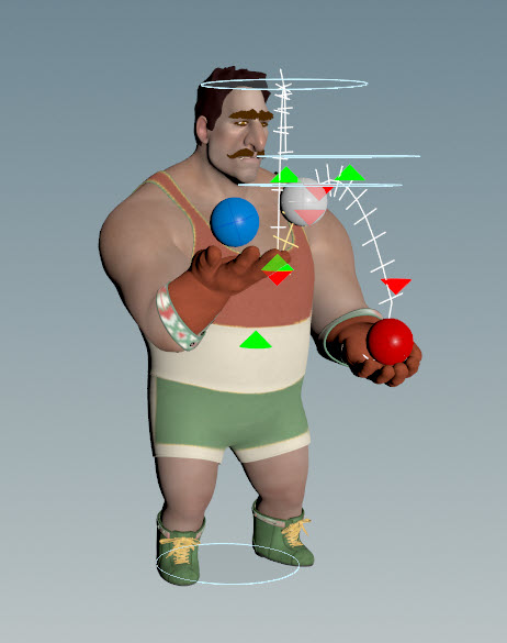
In advanced mode, the dynamic motion controls (start position, end position, and height) are displayed. You could set the visibility of these controls using selection sets - the dynamic motion controls are found under All Controls ▸ dynamicmotion.
-
Adjust the height of the dynamic motion by selecting the height plane that appears at the top of the dynamic motion arc, and adjusting the handles:
Change height of dynamic motion arc Note
Select the height plane and press R to switch the transform handle to rotate mode. This allows you to rotate the plane so that the dynamic motion path skims the plane instead of reaching a specific height.
-
Change the start or end position of a dynamic motion section by selecting the green/red arrow at the start/end of the dynamic motion path, and adjusting the position using the handle:
Change dynamic motion end position
If you try to switch to another animation layer while in advanced mode, a prompt will appear with the following options:
Switch to <new layer>
Applies the dynamic motion changes to the new layer, and resets the current layer to the original animation.
Remain on <current layer>
Stays on the current animation layer.
Bake to new layer
Creates a new layer with the changes from the current layer.
Reset Dynamic Motion
Removes all dynamic motion, resetting the dynamic motion tool to its original state.
Note
If you switch from advanced mode to basic mode, any changes made in advanced mode since the last bake is discarded.
| To... | Do this |
|---|---|
|
Display the entire dynamic motion path |
In the settings HUD, Dynamic Motion Settings ▸ Path Settings tab, turn off Limit Number of Frames. |
|
Limit the number of frames shown on the dynamic motion path |
In the settings HUD, Dynamic Motion Settings ▸ Path Settings tab, turn on Limit Number of Frames, and adjust the Frame Before and Frame After values. |
|
Adjust the height of the dynamic motion |
Select the height plane that appears at the top of the dynamic motion arc, and adjust the height using the handles. or
|
|
Change the start or end position of the dynamic motion section |
Select the green/red arrow at the start/end of the dynamic motion path, and adjust the position using the handle. |
|
Put the dynamic motion back onto the animation |
|
|
Add additional keyframes to the dynamic motion regions |
|
|
Display the controls for all the dynamic motion paths |
You could also set the visibility of the dynamic motion controls using selection sets, found under All Controls ▸ dynamicmotion. |
|
Remove a section of dynamic motion |
|
|
Remove all dynamic motion |
|
|
Change the size of the dynamic motion path ticks |
⇧ Shift + |
|
Change the size of the dynamic motion height planes |
⌃ Ctrl + |
Ragdoll 
The ragdoll tool allows you to add a ragdoll simulation to your animation. To enter the ragdoll tool, click ![]() Ragdoll on the top toolbar, or select Ragdoll from the radial menu (press C over the viewport).
Ragdoll on the top toolbar, or select Ragdoll from the radial menu (press C over the viewport).
In this example, we add a ragdoll simulation to the ![]() Electra test geometry.
Electra test geometry.
Setup 
Before using the ragdoll tool, perform the following setup steps:
-
Update the Electra skeleton with a set of joint limits.
-
Create ragdoll collision shapes for Electra.
-
Add the collision shapes to the list of Electra character elements.
-
Map the controls on Electra’s rig to points on Electra’s skeleton.
-
(Optional) Set the ragdoll configurations used by the animate state.
See ragdoll simulations for more information.
Note
The Configure Ragdoll parameter on the Electra test geometry performs all the above setup steps automatically.
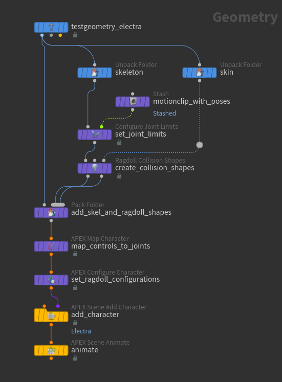
-
On the
 Electra test geometry, set the Output parameter to APEX Character.
 -
Set joint limits on the Electra skeleton:
-
The
 Unpack Folder SOP,
 skeleton, extracts the skeleton from Electra. Set the Extract Pattern parameter to/Base.skel. -
The
 Configure Joint Limits SOP sets joint limits on the Electra skeleton. See set joint limits for more information.
-
-
Create ragdoll collision shapes:
-
The
Unpack Folder SOP, skin, extracts the skin geometry from Electra. Set the Extract Pattern parameter to/Base.shp. -
The
 Ragdoll Collision Shapes SOP creates collision shapes for Electra. See create collision shapes for more information.
Note
In the SOP workflow for ragdoll simulations, the
 Rig Stash Pose SOP creates the rest pose for the character by storing the
 rest_transformattribute that is used later by the ragdoll solver. In contrast, the ragdoll solver in the animate state reads the rest transform from the rest skeleton,Base.skel. However, a warning is still displayed on the Configure Joint Limits and Ragdoll Collision Shapes SOPs stating that no rest transform is configured, but this warning can be ignored. -
-
The
 Pack Folder SOP adds the updated skeleton (with joint limits) and ragdoll collision shapes to the set of character files.
 Set the Name and Type parameters to:
-
Updated skeleton: Name =
Base, Type =skel. -
Ragdoll shapes: Name =
RagdollCollision. The Name and Type parameters for the ragdoll shapes can be set to anything.
See assemble character data for information about naming character elements in the packed character format.
-
-
The
 APEX Map Character SOP maps Electra’s rig controls to skeleton joints. This is so that the ragdoll motion can be baked back onto the rig controls.
 -
Set Rig Path to
/Base.rig. -
Set Skeleton Path to
/Base.skel. -
Keep Map By Name turned on, so that the APEX Map Character SOP automatically performs a mapping between controls and joints that share the same name.
-
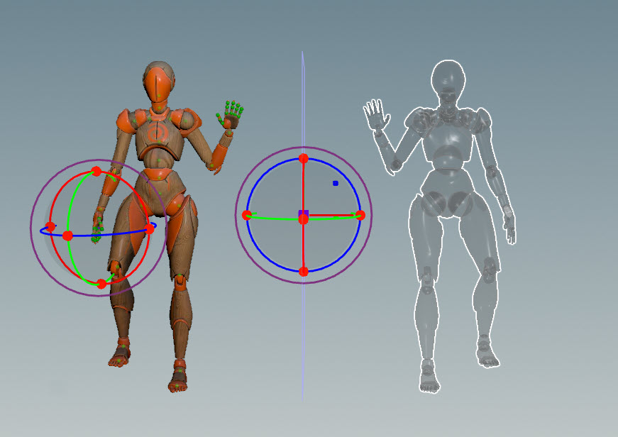
Enter the Map Character viewer state - select the APEX Map Character SOP, turn on its display flag, and press Enter over the viewport.
-
In the viewer state, click between the controls and skeleton joints. Entries in the Mappings multiparm will be automatically created.
Map character rig controls to skeleton joints
-
-
(Optional) The
 APEX Configure Character SOP configures ragdoll properties on the character.
 If this node is included in the ragdoll setup, a ragdoll for the character is automatically created in the ragdoll tool. Otherwise, you will need to manually create a ragdoll in the animate state.
Click
beside Ragdoll Configurations. The Character Name is the name of the ragdoll that will appear in the animate state selection sets HUD. -
The
 APEX Scene Add Character SOP adds the character files to an animation scene. Set the Character Name parameter to
 Electra.
Manually create a ragdoll 
If an APEX Configure Character SOP is not used in the ragdoll setup, you will need to manually create a ragdoll and specify the ragdoll configuration information in the prompts that come up.
-
Enter the animate state - select the
 APEX Scene Animate SOP, turn on its display flag, and click Animate on the left toolbar or press Enter over the viewport.
 -
Enter the ragdoll tool.
-
Press H to start creating a ragdoll simulation.
-
Enter a name for the ragdoll and click OK.
Warning
Only names without spaces are supported.
Note
Enter a name that is different from the character. If the character and ragdoll names are the same, the ragdoll collision shapes will be added under the actual character in the selection sets.
-
In the Character Source Data window, select the skeleton (.skel) of the character you want to turn into a ragdoll. Click Accept.
-
Select the ragdoll collision shapes that were previously set up for the character.
The collision shapes are generated by the 2nd output of the Ragdoll Collision Shapes SOP. If these collision shapes are packed into the character and named, say,
RagdollCollision, then select RagdollCollision, which appears under the character (.char).If you bring in a copy of a character that is already in the scene, but this new character doesn’t already have collision shapes, you can use the collision shapes from the original character.
-
Click Accept.
-
Specify the output skeleton from the character rig graph. This is the deformed skeleton.
We want the ragdoll to inherit the original animation of the character before the ragdoll simulation takes over. On the character rig, the movement of the skeleton is driven by the animation. The skeleton input of the rig is in its rest pose. The skeleton output of the rig has updated joint positions that are driven by the animation. This skeleton output is used to build a MotionClip, which stores a set of skeleton poses over a frame range.
In the dialog, specify the skeleton output (.skel) of the character rig. The character format hierarchy is as follows: character > rig > rig output node > skeleton output. For example:
character -- Base.rig -- output -- Base.skel -
Click Accept. You will see the character’s collision shapes overlaid on top of the character.
Default ragdoll simulation 
Once the Electra ragdoll has been set up, there will be an entry for both the Electra character and Electra ragdoll in the selection sets HUD, under All Controls.
Note
The Electra ragdoll only appears in the selection sets if you are in the ragdoll tool.
To turn off the display of the ground plane:
-
Press ⌃ Ctrl + G to open the settings HUD.
-
In the Ragdoll Settings ▸ Solver tab, turn off Ground Display.
To have a better view of the ragdoll collision shapes, use the handle to offset the ragdoll from the original animation:
Note
If the ragdoll handle doesn’t appear, press ⌃ Ctrl + G to open the settings HUD, and in the Ragdoll Settings ▸ Actions tab, turn on Show Visualiser Offset Handle.
If you play the animation, the ragdoll will fall on the ground plane, which is the default behavior for a ragdoll:
Working with props 
To get a prop to work with ragdoll, you need to turn the prop into a “character”. In this example, we add a thin box platform to the scene for Electra to stand on:
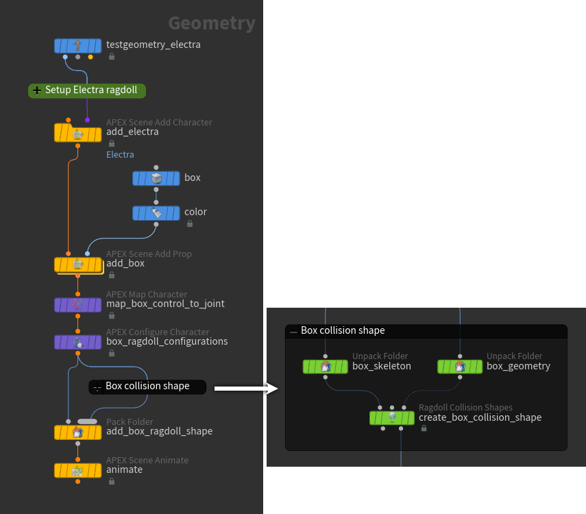
-
The
APEX Scene Add Prop SOP turns the prop into a character and adds it to the scene.-
The Prop Name parameter specifies the name of the prop character that will appear in the selection sets HUD. In this example, we set Prop Name to
box_prop. -
In the rig tree view, we can see that the APEX Scene Add Prop SOP creates a box character (.char) that contains a skeleton, rig, and skin.
-
-
The
APEX Map Character SOP maps the box’s one control to its joint.-
Set Rig Path to
/box_prop.char/Base.rig. -
Set Skeleton Path to
/box_prop.char/Base.skel.
-
-
(Optional) The
APEX Configure Character SOP configures ragdoll properties on the box. If this node is included in the ragdoll setup, a ragdoll for the prop is automatically created in the ragdoll tool. Otherwise, you will need to manually create a prop ragdoll in the animate state.
-
Set Rig Path to
/box_prop.char/Base.rig. -
Click
beside Ragdoll Configurations. The Character Name is the name of the prop ragdoll that will appear in the animate state selection sets HUD.
Note
By default, the Skeleton Path and Collision Shapes Path are relative to the character (.char) in the packed folder structure (seen in the rig tree view).
-
-
Create the ragdoll collision shape for the box:
-
The
Unpack Folder SOP, box_skeleton, extracts the box skeleton. Set the Extract Pattern parameter to/box_prop.char/Base.skel. -
The
Unpack Folder SOP, box_geometry, extracts the box geometry. Set the Extract Pattern parameter to/box_prop.char/Base.shp. -
The
Ragdoll Collision Shapes SOP creates the collision shape for the box. See create collision shapes for more information.
Note
If the prop has a concave surface, in the Ragdoll Collision Shapes viewer state, set Shape to Convex Hull, and Algorithm to Convex Decomposition. In the G HUD, adjust the Max Concavity to more closely match the shape of the prop.
-
-
The
Pack Folder SOP adds the ragdoll collision shape to the set of character files for the box:-
Set the Parent Folder parameter to
box_prop.char. -
The Name and Type parameters for the box ragdoll shape can be set to anything. We set Name to
RagdollCollision.
Note
In contrast to the ragdoll setup for Electra, joint limits are not necessary for our box prop. As a result, the skeleton for the box is not updated with joint limits, and so we don’t need to add the box skeleton back into the set of character files.
-
-
Enter the ragdoll tool in the animate state, and play the simulation:
Starting ragdoll simulation -
Use the handles to pose Electra on top of the box.
-
Update the ragdoll collision shapes to match the pose on Electra:
-
Press ⌃ Ctrl + G to open the settings HUD.
-
In the Ragdoll Settings ▸ Actions tab, click Reload Target Animation.
-
In the Reload Target Animation window that pops up, select the Electra ragdoll.
-
Click Accept.
Pose Electra on box -
-
Set the box to not be actively simulated ragdoll:
-
Select the box ragdoll.
-
Press ⌃ Ctrl + E to toggle the active state of the box ragdoll.
or
Press G to open the parameters HUD. In the Ragdoll ▸ Animated tab, turn off Active.
-
-
Increase the stiffness of Electra’s joints:
-
In the selection sets HUD, select the Electra ragdoll. This selects all of Electra’s collision shapes.
-
Press G to bring up the parameters HUD.
-
In the Ragdoll ▸ Animated tab, increase the Bend Stiffness.
-
-
Make the box slippery:
-
Select the box collision shape.
-
Press G to bring up the parameters HUD.
-
In the Ragdoll ▸ Constant tab, decrease the Friction.
Electra on prop -
Ragdoll on existing animation 
In this example, a ragdoll simulation is added to the top character in the existing animation:
Create the ragdoll motion 
-
Set up the top character for the ragdoll simulation.
-
Enter the ragdoll tool in the animate state. You will see the character’s collision shapes. If you play the animation, the ragdoll will fall on the ground plane, which is the default behavior for the ragdoll.
Starting ragdoll behavior -
To get a better view of the ragdoll, use the handle to move the ragdoll to the side of the original animation.

Visualize ragdoll -
Set the spine joints to follow the animation, while the rest of the character is simulated as ragdoll.
-
Select the collision shapes along the spine and press G to bring up the parameters HUD.
-
In the Ragdoll ▸ Animated tab, turn on Match World Transforms. The selected collision shapes will follow the original skeleton joints.
-
Alt click Match World Transforms to sets keysframes at the current frame for each of the selected collision shapes. Channels for the selected collision shapes will appear in the channel list appended with
_matchworldtransforms.
Partial ragdoll Tip
If the collision shapes are jittering, it could be that they are colliding against each other. Try turning off (and keying) Active instead of turning on Match World Transforms.
Collision shapes jittering -
-
Specify that the ragdoll simulation takes over at the end of the throw.
-
On the playbar timeline, go to the frame where you want the ragdoll simulation to take over.
-
Turn off Match World Transforms.
-
Alt click Match World Transforms to sets keysframes at the current frame for each of the selected collision shapes.
Switch to full ragdoll at the end of the throw -
Put the ragdoll simulation back onto the animation 
To put the ragdoll motion back onto the top Electra:
-
Select all the controls on the top Electra (select the top Electra from the selection sets HUD).
-
Press ⌃ Ctrl + G to bring up the settings HUD. In the Ragdoll Settings ▸ Actions tab, the following baking options are available for writing out the ragdoll motion to the animation:
Bake Keys
Adds a keyframe at the current frame.
Start Recording Poses
Sets keyframes on the selected frames or over a frame range.
After clicking Start Recording Poses:
-
If you select certain frames on the playbar timeline, keyframes will be added at those frames.
-
If you scrub the timeline, keyframes will be added to every frame in the frame range while scrubbing.
-
If you press the
Play button on the playbar, keyframes will be added to every frame until you press the Stop button.
Bake Keys to New Layer
When turned on, adds the new keyframes for the ragdoll motion to a new animation layer that is set to be an override layer (the new layer overrides the base animation). This option is turned on by default.
-
-
Go to the frame on the timeline to start putting the ragdoll motion back onto the animation.
-
Click Start Recording Poses.
-
Scrub the timeline to the end of the ragdoll motion.
-
Click Stop Recording Poses. The ragdoll motion is added to a new animation layer as an override layer. We only started recording poses after the throw, so the original animation on the top Electra doesn’t show through the new layer:
Ragdoll motion written out as animation layer -
To have the ragdoll motion apply to the animation only after the throw motion, set weights on the new layer.
Final animation
The options for putting ragdoll motion back onto the original animation are:
1) Turn on Bake Keys to New Layer, and only record poses or bake keys within the frame range of the ragdoll motion. On the new animation layer that is created, set weights on the new layer. This is the same as the previous example.
2) Turn on Bake Keys to New Layer, and record poses or bake keys over the entire frame range of the animation and ragdoll motion. The entire frame range is written out to a new layer as an override layer.
3) Turn off Bake Keys to New Layer, and only record poses or bake keys within the frame range of the ragdoll motion. The ragdoll motion replaces the original animation within this frame range.
Ragdoll posing 
In ragdoll pose mode, you can manipulate controls to pose the character while the ragdoll simulation runs in the background.
In this example, we start with the following scene:
-
In the ragdoll tool, press O to enter ragdoll pose mode.
-
(Optional) To turn off the display of the ground plane:
-
Press ⌃ Ctrl + G to open the settings HUD.
-
In the Ragdoll Pose Settings ▸ Solver tab, turn off Ground Display.
-
-
In the selection sets HUD, under All Controls, there are sets for the Electra character, the Electra ragdoll, the box prop, and the box ragdoll. In ragdoll pose mode, we manipulate the Electra character’s controls, along with the Electra and box ragdoll collision shapes. In the selection sets HUD:
-
Turn on the display of the Electra character’s controls (
). -
Turn on the display of the Electra and box ragdoll collision shapes (
). -
Turn off the display of the Electra character and box geometries (
). This makes it easier to see the ragdoll collision shapes.
-
-
By default, all the collision shapes in ragdoll pose mode are inactive - they do not react to other objects. When a control is selected, its associated collision shape becomes active. In the below video, the hand control is selected, and so the hand collision shape becomes active (turns a lighter grey color). The hand shape reacts to the box while the fingers remain inactive and go through the box:
Selected collision shape reacts to objects -
To have the fingers also react to the box, make the fingers active:
-
Select the finger collision shapes.
-
Press ⌃ Ctrl + E to toggle the active state of the collision shapes.
Fingers react to box Note
The character controls do not react to the collision shapes, so they appear to go through the box when the hand is being moved. Once the mouse is released, the controls snap back to the position of the collision shapes.
-
Electra pushes the box 
To have Electra push the box:
-
Set the box to be active:
-
Select the box ragdoll shape.
-
Press ⌃ Ctrl + E.
-
-
Select and move the hand control:
Electra pushes the box -
Gravity can be applied to active objects in ragdoll pose mode:
-
Select the control for the box ragdoll shape.
-
Scroll down on the
 to apply gravity. Hold ⌃ Ctrl while scrolling to increase the gravity strength.
Apply gravity to box ragdoll shape -
-
Exit ragdoll pose mode by pressing O. Any controls and collision shapes that have moved in ragdoll pose mode have keyframes written out to their corresponding controls. (Turn on the display of the Electra character and box geometries
if it was previously turned off for ragdoll pose mode.)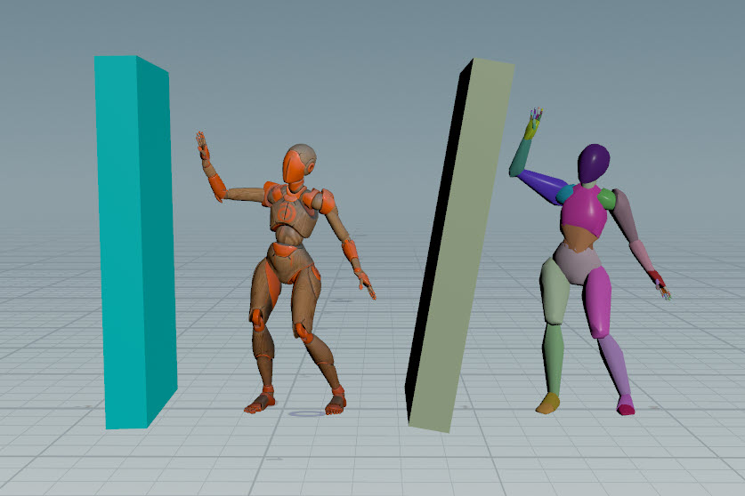
After exiting ragdoll pose mode -
To update the ragdoll to match the character pose:
-
Press ⌃ Ctrl + G to bring up the settings HUD.
-
Select Ragdoll Settings ▸ Actions.
-
Click Reload Target Animation.
-
In the dialog that pops up, select the Electra and box ragdolls.
-
Click Accept.
Update ragdoll to match character pose -
| To... | Do this |
|---|---|
|
Start creating a ragdoll |
Press H and follow the prompts. |
|
Remove a ragdoll |
|
|
Display the ragdoll off to the side of the character |
|
|
Visualize the ragdoll with the character skin or collision shapes |
|
|
Bring in props that can collide with the ragdoll |
See working with props. |
|
Toggle the active state of a collision shape |
This is the same as:
|
|
Set certain collision shapes to follow the original animation |
Other objects can still collide against the collision shape. |
|
Set certain joints to match the joint positions of the original skeleton |
The selected joints will follow the original skeleton joints, while the rest of the character will be ragdoll. |
|
Set a character to be a ragdoll at a particular frame |
|
|
Set certain collision shapes to not collide with other shapes |
|
|
Add the ragdoll motion to a new animation layer |
For more information, see put the ragdoll simulation back onto the animation. |
|
Reload the animation in the scene |
|
|
Set keyframes on ragdoll parameters |
|
|
Change the density, bounce, and friction of the collision shapes |
|
|
Copy and paste collision shape parameter values |
|
|
Reset the collision shape parameter values |
|
|
Pin unattached collision shapes to the skeleton |
This is a global option that applies to all the characters. See pin root of unattached collision shapes for an example. |
|
Show the collision shapes that intersect |
|
|
Apply gravity to an active object in ragdoll pose mode |
|
|
Turn on or off the ground plane |
|
|
Show or hide the ground plane |
|
Descriptions for the ragdoll parameters in the parameters HUD (G hotkey, Ragdoll tab) can be found in the ![]() Ragdoll Solver SOP node doc.
Ragdoll Solver SOP node doc.
How-to 
| To... | Do this |
|---|---|
|
Copy animation from one animation scene to another |
You can copy animation between characters that have the same selection set:
|