| On this page |

The animate state is a viewer state that can display multiple characters in a scene and allow users to perform posing such as FK or IK for characters, interact with character controls, and create constraints between characters. The animate state can interpret and evaluate an APEX graph, and display the evaluated output in the viewport. This page gives examples of graph logic for specific functionality in the animate state, such as creating controls and constraints, and defining joint hierarchies.
Note
We will use the term rig or rig graph to refer to a graph that has controls and geometry that an animator can interact with in the animate state. The term graph is more generic and can have purposes beyond an interaction element for animation.
Only data in the packed character format can be displayed in the animate state. Once you finish building up a rig graph, you need to add the graph to a packed folder structure in order for it to be picked up and displayed in the animate state.
The examples in this file demonstrate how to use APEX graphs to build functionality for the animate state.
Controls 
A control is something that a user can interact with in the animate state. In this example, we introduce a special APEX node, TransformObject. TransformObject manages the transform behavior of elements, including defining transform hierarchies between elements. It also handles animation-friendly transform component inputs like translation, rotation, and scale, with a defined rotation order. When a TransformObject node is put in a graph, and its parameters are promoted (connected to the graph’s input node), the TransformObject element is picked up by the animate state and turned into a control - it is displayed as something the user can interact with. In the following example, we create a control for a geometry.
Rig logic 
The graph below adds a control for a torus geometry:
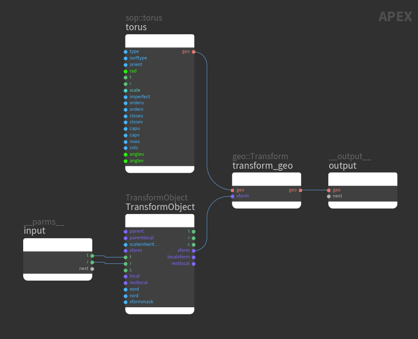
input
The graph input node - the node that takes in the input parameters.
output
The graph output node.
torus
The torus geometry to move around.
TransformObject
Defines and manages hierarchical transform behavior. To manipulate transforms in the animate state, the desired input parameters on the TransformObject node must be promoted, which is done by connecting the parameters to the graph input node. Once a TransformObject parameter is promoted, that TransformObject element is turned into a control.
In the example above, the translate (t) and rotate (r) parameters are promoted, so the user has access to the translate and rotate components of the control in the animate state.
transform_geo
Changes the position of the torus.
Evaluate the rig logic 
In the viewport, the graph itself is represented as geometry:
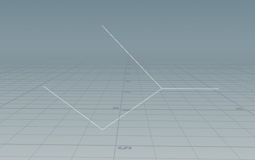
To see the output of the graph, you need to enter the animate state. The animate state automatically interprets the graph, creates controls for the promoted parameters, and displays the evaluated output. To enter the animate state:
-
Connect the node network as follows:

Network to enter animate state The
Pack Folder SOP assembles the rig into a packed folder structure. Only character elements in this packed character format can be displayed in the animate state.
-
On the Pack Folder SOP, the Name parameter is automatically populated when an input is connected to the SOP. Specify the Type of the input as
rig.rigis a special extension that tells the animate state that the input contains rig logic. -
Select the
APEX Scene Animate SOP and click
Animate on the left toolbar.
In the video below, we are in the animate state. The white dot in the middle of the torus is the control. When the control is clicked, the translation and rotation handles are displayed because those parameters are promoted. When you interact with controls in the animate state, the promoted parameters are modified, and these parameters are used as inputs to the graph logic. Every time you drag a control, the graph is evaluated with the updated parameters.
Interacting with a control in the animate state
Parent-child hierarchy 
In this example, we create a parent-child node hierarchy.
Rig logic 
We start with the torus control rig from the previous example and add a child control (red nodes are new):
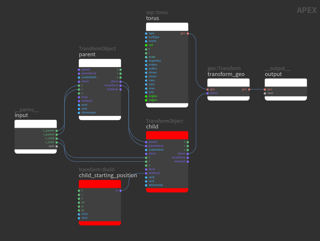
child
A TransformObject node with connections to its parent and parentlocal inputs is the child in a parent-child hierarchy. To create a parent-child hierarchy, make the following connections:
-
Parent TransformObject xform output → Child TransformObject parent input
-
Parent TransformObject localxform output → Child TransformObject parentlocal input
child_starting_position
Creates an offset for the child TransformObject node so that the parent and child controls don’t sit directly on top of each other. To change the transform of the child control:
-
Select the transform::Build node and press P to open the node parameter window.
-
Set the x-component of the transform parameter, t, to something like
1.0.
Connect child_starting_position to the restlocal input of the child TransformObject node. restlocal defines the starting position of the child control in reference to the parent control - it is an offset to the parent control.
Evaluate the rig logic 
To see the parent-child hierarchy of controls, enter the animate state. In the video below, the dot on the left is the parent control, and the one on the right is the child control:
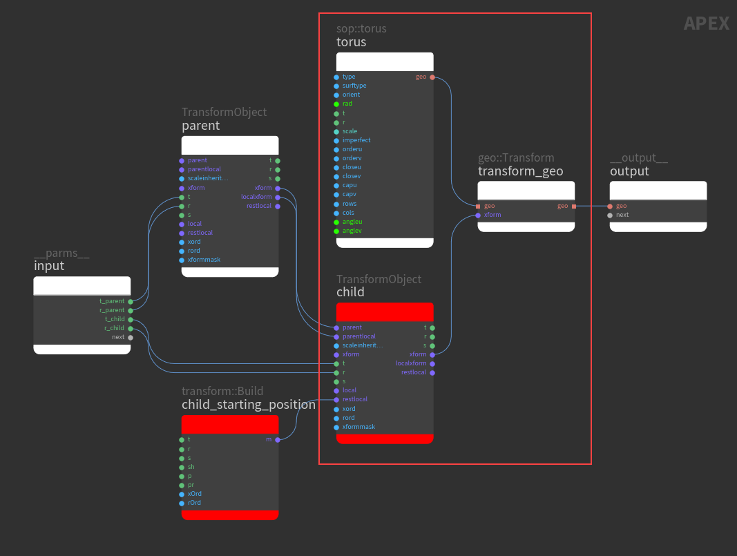
The center of the torus sits at the child control because the position of the torus is driven by the child control:
Constraints 
In this example, we show how to break the parent-child behavior by creating a constraint.
Rig logic 
-
We start with the parent-child rig from the previous example and add a second child control (red nodes are new):

Create a second child control In the video below, the left control is the parent, the middle control is the first child, and the right control is the second child. Both child controls follow the parent:
Both child controls follow the parent -
In the graph below, the
child2TransformObject control is constrained to a specific position:
Constrain the second child control child2The TransformObject’s xform input is the world space transform and it overrides all the other inputs. If you connect something to the xform input, it will act like a constraint.
Note
If a TransformObject is wired up as a child in a hierarchy, and you connect something to its xform input, the TransformObject will no longer follow its parent but be constrained to the xform position.
Evaluate the rig logic 
In the video below, the child control in the middle follows the parent (left control) because it is not constrained. The child control on the right is in a parent-child hierarchy, but does not follow the parent because it has an xform input that constrains it to the xform position:
Note
If a TransformObject is a child in a hierarchy and is also constrained (has a connection to its xform input), its localxform output will have a completely different value than if the TransformObject was not parented. The local space is now “counter-animating” the movement of the parent to keep the control at its constrained position.
Constrain one transform component 
To constrain one particular transform component (translate, rotate, or scale) and keep the other components unchanged, use the xformmask port on the TransformObject node.
In this example, we start with a 3-joint tube geometry and build a network similar to the bone deformation example. The pink nodes add the functionality of using a bit mask to constrain specific transform components to a driver (something that drives the transforms of a joint or control):
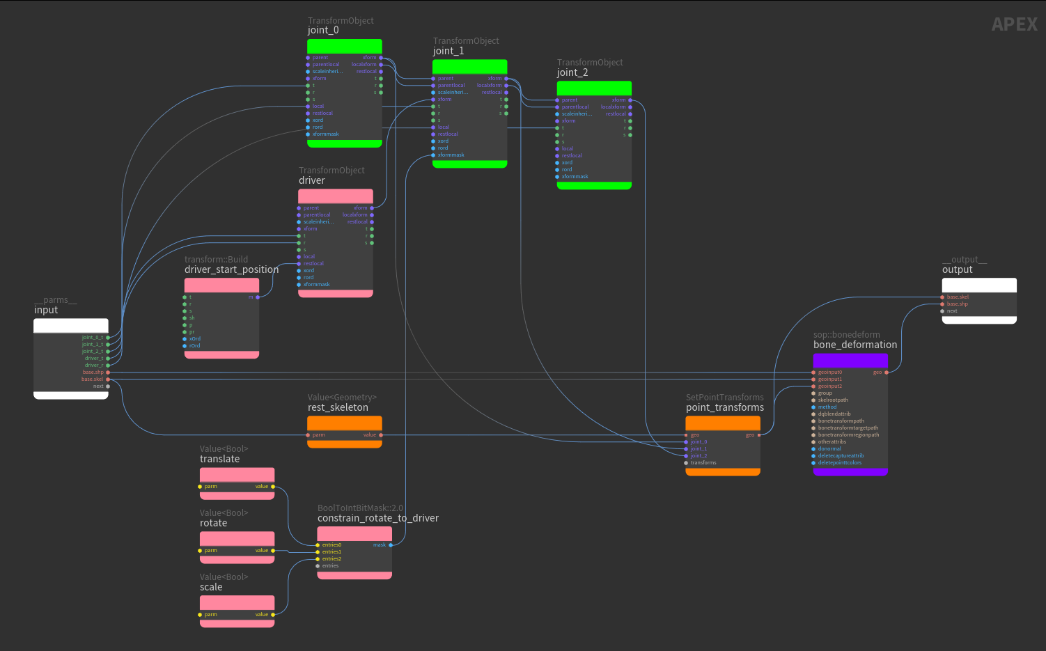
joint_1 and constrain_rotate_to_driver
On joint_1, the xformmask input works in combination with the xform input to override specific components of the transformation. In this example, we constrain the rotation of joint_1 to the driver's rotation by setting the following values in the bit mask:
-
rotateValue node =True -
translateandscaleValue nodes =False
driver
The translate and rotate values on the driver TransformObject node are promoted as controls and have the following functionality:
-
When the translate control of the
driveris changed,joint_1on the skeleton does not move because thejoint_1translate is not constrained to the driver. The tube geometry does not deform. -
When the rotate control of the driver is changed, the rotation of
joint_1updates along with the driver because thejoint_1rotate is constrained to the driver’s rotation. The tube geometry deforms with thejoint_1rotation.
In the video below, when the driver translate is changed, the tube geometry does not deform. When the driver rotate is changed, the tube deforms with the rotation:
Abstract controls 
An abstract control is a control that can drive a float value or be used as a pivot point in the rig for posing purposes. An abstract control is not associated with a transform, unlike the controls created from TransformObject nodes. In the viewport, the interaction behavior of an abstract control is different from a regular control. For an abstract control, users drag the control to drive a float value. For a regular control, a transform handle is available to position and manipulate the control.
The AbstractControl graph node does not affect the functionality of the rig logic, nor does it get executed. It sits at the position specified by its xform input, and depending on its other input port connections, it either drives a value or is used as a pivot point.
In this example, we start with a 5-joint tube geometry and build a network similar to the bone deformation example:
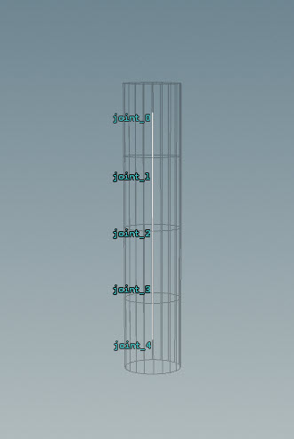
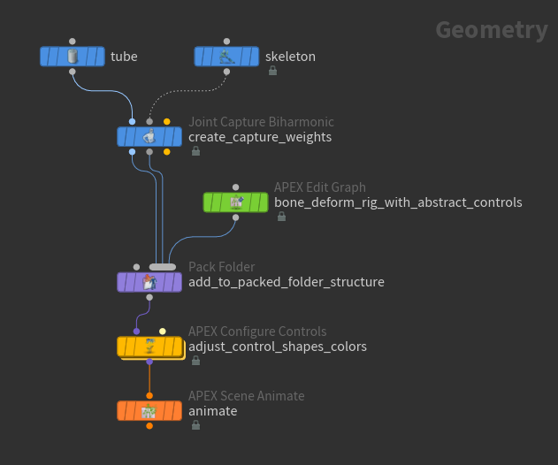
Two abstract controls are added to the bone deformation rig logic:
-
A pivot that sits at
joint_4(red node). -
A control that sits at
joint_2and drives the scale of the tube geometry aroundjoint_2(blue nodes).
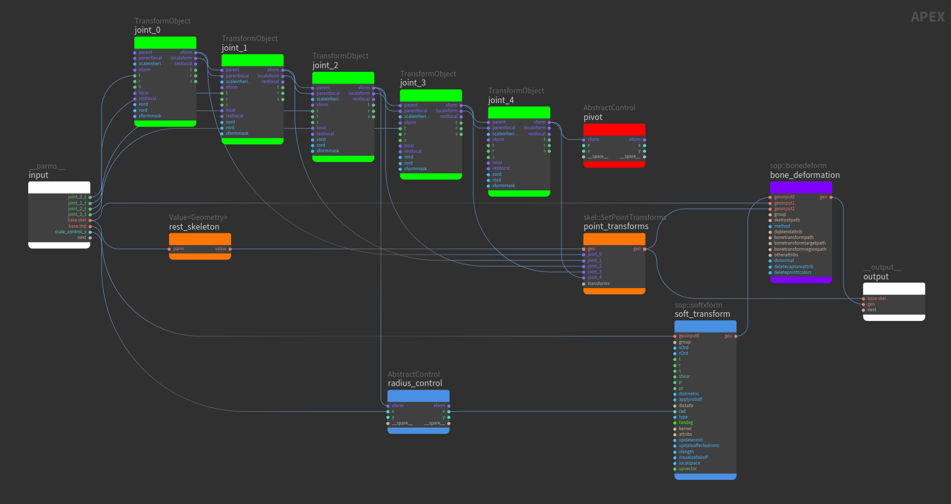
joint_*
The joint_* TransformObject nodes are connected in a parent-child hierarchy. The translate parameter, t, of joint_0, joint_1, joint_2, and joint_3 are promoted. An abstract control sits at the position of joint_4, so we don’t promote any joint_4 parameters.
pivot
If something is connected to the xform input of an AbstractControl node, and its x and y input ports are unconnected, the AbstractControl node is interpreted by the viewport as a control that can be used as a pivot. The input to the xform port could come from any node as long as the input is a matrix, so that the AbstractControl node knows where to place the control.
In this example, the xform output of joint_4 is connected to the xform input of pivot, so the pivot abstract control sits at the position of joint_4. Even though joint_4 is the lowest joint in the joint hierarchy, the abstract pivot control at joint_4 can be used to drive the joints that are higher up on the joint chain.
The following behavior can be seen in the animate state:
-
Select the
APEX Scene Animate SOP in the network editor and turn on its display flag.
-
Click
Animate on the left toolbar.
soft_transform
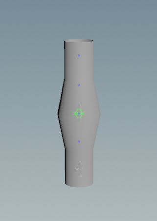
The sop::softxform node moves a specified group of points, as well as their neighboring points. In this example, we increase the scale of the points around
joint_2:
-
In the group parameter, specify the points in the geometry to transform. In this example, group is set to the geometry points around
joint_2. -
Set the s parameter to values greater then
1.0. This increases the size of the tube aroundjoint_2.
radius_control
If the x or y input/output port of an AbstractControl node is connected in the “path” of a promoted value, dragging on the abstract control in the horizontal or vertical direction drives the promoted value.
The radius parameter, rad, on the soft_transform node is promoted. The radius_control abstract control sits at the position of joint_2. Its input and output ports x are connected to the wire promoting the rad value, so radius_control drives the rad value. Dragging the abstract control in the horizontal direction affects the scale of points further from joint_2.
The following behavior can be seen in the animate state:
The following hotkeys change the drag behavior of the abstract control in the viewport:
Drag behavior |
Action |
|---|---|
Change control values by integer step size |
Hold ⌃ Ctrl while dragging. |
Change control values at a slower rate |
Hold ⇧ Shift while dragging. |
Change control values at a faster rate |
Hold ⌃ Ctrl + ⇧ Shift while dragging. |
Configure abstract controls 
Abstract control appearance 
To configure the size, shape, color, and position of abstract controls, use the APEX Configure Controls SOP:

-
In the APEX Configure Controls SOP, click
beside Control Configs to add a set of configurations for each abstract control:
-
Specify the rig to configure the abstract controls for in the Rig Source parameter. The name of the rig is set in the
Pack Folder SOP. See assemble character data for information on how to name the character elements within the Pack Folder SOP.
-
In the Control Group parameter, specify the name of the abstract control, or use the APEX path pattern syntax to specify groups of controls.
-
Turn on the desired Use Shape Override, Use Shapeoffset, and Use Color parameters.
-
-
To view the configured abstract controls, enter the animate state:
-
Select the
APEX Scene Animate SOP in the network editor and turn on its display flag.
-
Click
Animate on the left toolbar.
-
Abstract control properties 
Abstract control properties define how the control behaves in the viewport. These properties are stored in the properties dictionary attribute of the AbstractControl node. The properties dictionary contains a set of nested dictionaries with the following hierarchy:
control:
    parms:
        <property1>,
        <property2>,
        ...
control
A dictionary that contains information on how to configure the control, for example, how the control should look in the viewport and the default parameters of the control. Information on control shapes is also stored in this dictionary.
parms
Inside the control dictionary is another dictionary called parms, which stores the default parameters that determine the behavior of the control.
The table below lists the properties that can be configured for an abstract control:
Property |
Type |
Description |
|---|---|---|
x_min, x_max |
|
Defines the default minimum/maximum value for the control when dragging in the horizontal direction. If not defined, the default minimum and maximum values are -10 and 10. |
y_min, y_max |
|
Defines the default minimum/maximum value for the control when dragging in the vertical direction. If not defined, the default minimum and maximum values are -10 and 10. |
lock_range |
|
When set to |
Abstract control properties can be configured using the Attribute Adjust Dictionary SOP and
Attribute Wrangle SOP. The Attribute Adjust Dictionary SOP is used to create a dictionary of control properties. This dictionary is then set on the
properties attribute of the AbstractControl node using the Attribute Wrangle SOP:
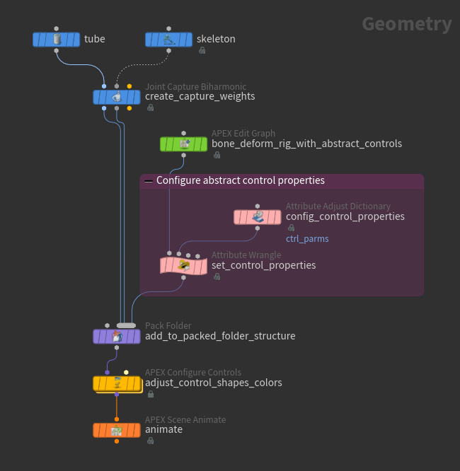
Attribute Adjust Dictionary SOP
Creates a dictionary of abstract control properties:
-
Specify the name of the dictionary in the Attribute Name parameter. This is the name that is used later by the Attribute Wrangle SOP to set the dictionary of control properties on the AbstractControl node.
-
Add a multiparm for each control property:
-
Click
beside Number of Entries.
-
For each property, specify the Key (name of the property), Type, and Value parameters. For example:
-
Key:
x_min -
Type: Float
-
Value:
0.001
-
-
Attribute Wrangle SOP
Sets the dictionary of properties on the abstract control’s properties attribute.
Set the Group parameter to @callback=AbstractControl. This is the graph node to set the properties for.
In the VEXpression textbox, enter the following VEX code:
dict parms = detail(1, '<Attribute Name parameter>');
dict ctrl;
ctrl['parms'] = parms;
d@properties['control'] = ctrl;
The <Attribute Name parameter> comes from the Attribute Adjust Dictionary SOP’s Attribute Name parameter.
Note
The dictionary created by the Attribute Adjust Dictionary SOP can be set to any name (in the Attribute Name parameter). However, the dictionaries within the abstract control’s properties attribute must be named control and parms, because the AbstractControl node picks up on these names when configuring the control’s properties.
The abstract control’s properties attribute can be viewed in the geometry spreadsheet:
-
In the network editor, select the Attribute Wrangle SOP.
-
At the top of a pane, click the
New Tab icon and select New Pane Tab Type ▸ Inspectors ▸ Geometry Spreadsheet.
-
In the geometry spreadsheet, select
Points from the top toolbar since we want to see the attributes of an AbstractControl node, and a graph node is a point in the graph geometry.
-
For an abstract control (row with callback =
AbstractControl),click the entry under the properties column and select Inspect. Below is an example of the
propertiesattribute for an abstract control:{ "control":{ "parms":{ "lock_range":1, "x_max":2, "x_min":0.001, "y_max":2, "y_min":0.001 } } }
How-to 
| To... | Do this |
|---|---|
|
Add a control |
For the parameters you want to turn into controls, promote the input parameters on the corresponding TransformObject node by connecting the parameters to the graph’s input node. See the example for adding controls. |
|
Create a parent-child hierarchy |
Make the following connections between two TransformObject nodes:
See the example for creating a parent-child hierarchy. |
|
Set the starting position of the child control in reference to the parent control |
Connect a transform::Build node to the restlocal input of the child TransformObject node. See the example for creating a parent-child hierarchy. |
|
Create a constraint |
To constrain a TransformObject node to a driver, connect the driver to the xform input of the TransformObject node. See the example for creating a constraint. |
|
Constrain one transform component |
Use a BoolToIntBitMask node, and Value nodes for the translate, rotate, and scale components to create a bit mask that determines the particular transform component to constrain. Connect the BoolToIntBitMask node to the xformmask input of the TransformObject node you want to constrain. See the example for constraining one transform component. |
|
Change the drag behavior of the abstract control in the viewport |
Change the abstract control values by an integer step size - hold ⌃ Ctrl while dragging. Change the abstract control values at a slower rate - hold ⇧ Shift while dragging. Change the abstract control values at a faster rate - hold ⌃ Ctrl + ⇧ Shift while dragging. |