| On this page |
Overview 
An ONNX file represents a machine learning model. Machine learning usually consists of two stages: training (the process of building a model that can solve a problem) and inference (using that model to solve the problem). This node performs inference. It uses a pre-trained model on the node’s inputs to evaluate and then generate the outputs (the machine-learned solution).
Note
Model refers to the ONNX file and its inputs and outputs.
There are many systems that do training and these can require significant dependencies. However, the resulting model often consists of a few simple operations. The Open Neural Network Exchange ( ONNX ) format is a file format and inference engine that lets you use models trained in PyTorch or TensorFlow in a common framework.
An ONNX inference model consists of multiple inputs and outputs. Each input and output is a tensor, otherwise known as multi-dimensional data. The tensor is an array when it’s 1D, an image when it’s 2D, a volume when it’s 3D, and so on. You can set the dimension in the second cell of the Tensor Shape parameters.
Note
ONNX models can contain input and output types other than tensors, but this node currently supports only tensors.
The parameters in the Model tab relate to the ONNX file’s inputs and outputs, while the parameters in the Input & Output tab relate to the inputs and outputs of the node itself. The node inputs in the Input & Output tab pull in the input data for the Model tab, which you can configure in the Input & Output tab before you combine them in the model input in the Model tab. You can then further configure each model output in the Model tab before combining them in the node output in the Input & Output tab.
For information about how to use this node, see How to use ONNX Inference.
Setup Shapes from Model 
Use the Setup Shapes from Model parameter in the Model tab to populate most of the values required for this node. Along with adding input and output information in the Model tab based on the .onnx file, an input and output is made for each model input and output. The following are all the parameters that Setup Shapes from Model populates:
-
Model tab
-
Number of Inputs
-
Number of Outputs
-
Name
-
Data
-
Input Tensor Shape
-
Output Tensor Shape
-
-
Input & Output tab
-
Number of Inputs
-
Number of Outputs
-
Name
-
Data
-
Output Tensor Shape
-
Tensor shapes 
The model (ONNX file) interprets an image as a long strand of pixels, which forms a 1D array, instead of a tiled 2D image (see the following image). Use the parameters in this node to transform an input or output’s pixel coordinates so they match the model’s requirements.
The tensor shapes are the shape (size and data format) of the model’s input or output. The Input Tensor Shape and Output Tensor Shape parameters are a 3 x 3 table. For an image, you must set three values: the number of components, the width, and the height. When the first cell is set to 0, this is where the node stops parsing the shape. Set the first cell to 1 to multiply the values by 1. Set the first cell to -1 to make it a dynamically sized dimension where you can specify an unlimited amount of inputs or outputs. The use case for setting this to -1 is if your model can take in an arbitrary length of listed inputs or outputs. For example, your model can handle unlimited images and it runs the inference individually on each image. This is more common for a model that takes a position in space because you can feed it multiple sample points together.
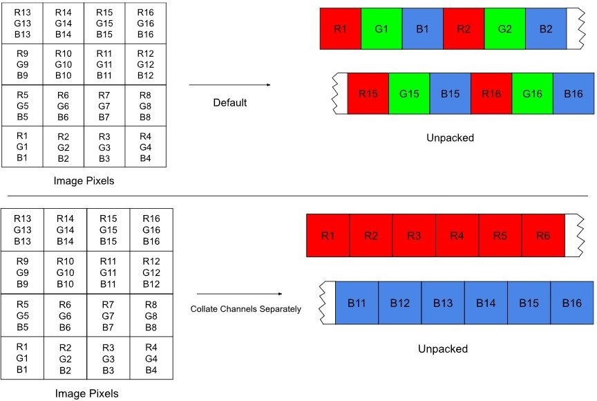
The Input Tensor Shape and Output Tensor Shape parameters are the shape of the input or output that the model requires. For example, this determines whether the data should be 3 x 224 x 224, which is an image with three (RGB) components. There are different options for how the data layout occurs. Sometimes the model expects RGB values either together in the same pixel or in separate layers (a separate image for each RGB channel). The Collate Channels Separately parameter lets you set how to split up pixels from an image to transform them into the data layout that the model expects. The following image shows how the node unpacks the pixels by default and when Collate Channels Separately is on.
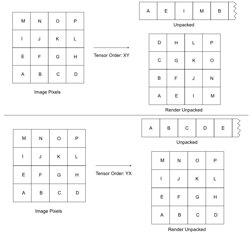
The Tensor Order determines whether the model unpacks the pixels vertically or horizontally. YX keeps the pixels in their original format (horizontal), while XY transposes the data layout to unpack the pixels vertically (see the following image). For example, when Tensor Order is YX the model expects a square image. When Tensor Order is XY and Input Tensor Shape is 224 x 224 x 3, the model expects a 224 x 224 image with RGB values together in each pixel.
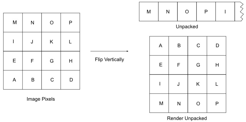
Most models are trained on 2D space, which expects the origin to be at the top left corner of the image instead of at the bottom left corner. Use the Flip Input Vertically and Flip Output Vertically parameters if you need to convert the pixel coordinates of an input or output in Houdini’s 3D space to 2D space so it matches the model. The following image shows how these parameters flip the pixels.
Parameters 
Model 
Model File
The name of the .onnx file to load. The model inputs and outputs must match the settings of the ONNX file.
Note
An error message appears when you set the Model File parameter but the input and output information in the Model tab is empty. Setting the other Model parameters resolves this error.
Reload Model
Forces a reload of the .onnx file.
Setup Shapes from Model
Reads the .onnx file to determine the number of inputs and outputs and their shapes.
See Setup Shapes from Model for more information.
Number of Inputs
The number of inputs to the model.
Note
The order of the inputs must match the order of the inputs in the ONNX model, as the node doesn’t match the model based on names.
Name
The name of the input to the model. The Setup Shapes from Model button populates this with the input name from the model, but you can rename it.
Data
The node input(s) that provide the data for this model input. You can enter a space- or comma-separated list of node input names to link multiple inputs together in a chain, such as separate R, G, and B layers.
Input Tensor Shape
The shape of the input that the model requires. The total shape must match the number of elements (the total size of the data) in the input.
A warning appears if the input image’s size doesn’t match the model’s expected input size. Use the Resample Size parameter to resize the input image.
See Tensor shapes for more information.
Tensor Order
Specifies how to convert the input image into the data layout that the model expects, which is a 1D tensor.
YX
Unpack pixels horizontally (neighboring samples along X are placed together).
XY
Unpack pixels vertically (neighboring samples along Y are placed together).
See Tensor shapes for more information.
Collate Channels Separately
When converting an image with multiple channels per pixel into a 1D tensor, this stores the RGB image as rrrgggbbb (separate RGB sets) and the shape’s first dimension is the number of channels.
If this parameter is off when converting an image with multiple channels per pixel into a 1D tensor, this stores the RGB image as rgbrgbrgb and the shape’s final dimension is the number of channels.
See Tensor shapes for more information.
Channel Size
The value that overrides the input image’s number of channels so it matches the channel size that the model expects.
Number of Outputs
The number of outputs to the model.
Note
The order of the outputs must match the order of the outputs in the ONNX model, as the node doesn’t match the model based on names.
Name
The name of the output of the model. The Setup Shapes from Model button populates this with the output name from the model, but you can rename it.
In the Input & Output tab, enter this name in a node output’s Data parameter so it uses this model output’s data.
Output Tensor Shape
The shape of the output that the model requires. The total shape must match the number of elements (the total size of the data) that the model generates.
See Tensor shapes for more information.
Tensor Order
Specifies how to convert the output image into the data layout that the model expects, which is a 1D tensor.
YX
Unpack pixels horizontally (neighboring samples along X are placed together).
XY
Unpack pixels vertically (neighboring samples along Y are placed together).
See Tensor shapes for more information.
Collate Channels Separately
When converting an image with multiple channels per pixel into a 1D tensor, this stores the RGB image as rrrgggbbb (separate RGB sets) and the shape’s first dimension is the number of channels.
If this parameter is off when converting an image with multiple channels per pixel into a 1D tensor, this stores the RGB image as rgbrgbrgb and the shape’s final dimension is the number of channels.
See Tensor shapes for more information.
Channel Size
The value that overrides the output image’s number of channels so it matches the channel size that the model expects.
Max Batch Size
Determines how many multiples of the input you want to evaluate together and process at once. If you have multiple input instances, set this parameter to split the inputs into batches so the model runs them in succession to reduce peak memory usage.
This parameter doesn’t correspond to the amount of pixels in the image, but instead depends on what size the rest of the input is. For example, if you had a model that only accepts an image as a single input, this parameter value is how many images you batch together at once.
Note
This parameter applies to only the first dynamic dimension.
Enable CUDA
Uses CUDA to perform inference on the GPU (requires CUDA and cuDNN). Turn this on if you want faster results.
If CUDA is not set up, you’ll receive a warning and the node performs inference on the CPU.
Input & Output 
Number of Inputs
The number of inputs for the node.
The Setup Shapes from Model button creates a node input for each model input and associates them using the model’s Data parameter.
Name
The name of the node input. The Setup Shapes from Model button populates this, but you can rename it.
In the Model tab, enter this name in a model input’s Data parameter so it uses this node input’s data.
Type
The data type for the node input.
Tensor Order
Specifies how to convert the input image into the data layout that the model expects, which is a 1D tensor. This value applies only when you enter multiple input names in a Data parameter in the Model tab, as it changes this input’s layout before combining it with the other inputs.
YX
Unpack pixels horizontally (neighboring samples along X are placed together).
XY
Unpack pixels vertically (neighboring samples along Y are placed together).
See Tensor shapes for more information.
Flip Input Vertically
Flips the input image vertically. You can use this for models (2D images) that expect the origin to be at the top left corner of the image instead of at the bottom left corner.
See Tensor shapes for more information.
Collate Channels Separately
Stores an RGB image as rrrgggbbb and the shape’s first dimension is the number of channels. When off, this stores an RGB image as rgbrgbrgb and the shape’s final dimension is the number of channels. This parameter applies only when you enter multiple input names in a Data parameter in the Model tab, as it separates this input’s channels before combining it with the other inputs.
When converting an image with multiple channels per pixel into a 1D tensor, the channel values can either be interleaved or placed one after another.
See Tensor shapes for more information.
Resample Size
Resamples the input image to the specified dimensions (width by height). Use this parameter to match the model’s expected size for an input image, which is based on the Input Tensor Shape.
Set the width or height to -1 and the other cell to a specific value when you want the node to preserve the aspect ratio based on the specified dimension. For example, if you set the width to 224 and the height to -1, the node resizes the image’s height to a dimension that maintains the aspect ratio.
Filter
When Resample Size is on, this is the filter to use when resampling the input image.
Brightness Multiplier
Adjusts the brightness of the input image.
This is useful for models that expect colors to be represented by integers between 0 and 255, rather than floating-point values between 0 and 1. These models require scaling up of the input image’s brightness and scaling down the output image’s brightness.
1
Maintains the brightness as the input’s default amount.
255
Scales the brightness up by 255.
1/255
Scales the brightness down by 1/255.
Deduce Output Shapes from Data String
Populates the Output Tensor Shape and Channel Size for each output that has Auto Deduce Output Shape on. The values are based on the output’s Data parameter.
This parameter is useful if you want to calculate the tensor shape and channel size when merging multiple model outputs. The Setup Shapes from Model parameter automatically triggers this parameter.
Note
This parameter uses the input and output data from the Model tab, so you must populate those Model parameters before using this parameter.
Number of Outputs
The number of outputs for the node.
The Setup Shapes from Model button creates a node output for each model output and associates them using the node output’s Data parameter.
Name
The name of the node output. The Setup Shapes from Model button populates this, but you can rename it.
Type
The data type for the node output. When set to Infer, the output’s Output Tensor Shape and Channel Size parameters determine the data type.
Data
The name of the model output(s) to use as the data in this node output. You can enter a space- or comma-separated list of model output names to combine multiple outputs together.
Auto Deduce Output Shape
Makes the Deduce Output Shapes from Data String parameter affect this output.
Output Tensor Shape
The shape of the output. The total shape must match the number of elements (the total size of the data) that the model generates.
See Tensor shapes for more information.
Tensor Order
Specifies how to convert the output image into the data layout that the model expects, which is a 1D tensor.
YX
Unpack pixels horizontally (neighboring samples along X are placed together).
XY
Unpack pixels vertically (neighboring samples along Y are placed together).
See Tensor shapes for more information.
Flip Output Vertically
Flips the output image vertically. You can use this for models (2D images) that expect the origin to be at the top left corner of the image instead of at the bottom left corner.
See Tensor shapes for more information.
Collate Channels Separately
Stores an RGB image as rrrgggbbb and the shape’s first dimension is the number of channels. When off, this stores an RGB image as rgbrgbrgb and the shape’s final dimension is the number of channels.
When converting an image with multiple channels per pixel into a 1D tensor, the channel values can either be interleaved or placed one after another.
See Tensor shapes for more information.
Channel Size
The value that overrides the output image’s number of channels so it matches the channel size that the model expects.
Brightness Multiplier
Adjusts the brightness of the output image.
This is useful for models that expect colors to be represented by integers between 0 and 255, rather than floating-point values between 0 and 1. These models require scaling down the output image’s brightness after scaling up the input image’s brightness.
1
Maintains the brightness as the output’s amount.
255
Scales the brightness up by 255.
1/255
Scales the brightness down by 1/255.
Inputs 
n_input#
The source layer on which to apply ONNX inference. The amount of node inputs and their details are based on the Number of Inputs information in the Input & Output tab, which makes the inputs dynamic.
Outputs 
n_output#
The output layer with ONNX inference applied. The amount of node outputs and their details are based on the Number of Outputs information in the Input & Output tab, which makes the outputs dynamic.